
How to Use KY-011: Examples, Pinouts, and Specs
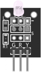
 Design with KY-011 in Cirkit Designer
Introduction
The KY-011 is a temperature and humidity sensor module that utilizes the DHT11 sensor. It provides accurate readings of ambient temperature and humidity levels, making it suitable for various environmental monitoring applications. The module is widely used in weather stations, home automation systems, and industrial monitoring setups due to its reliability and ease of use.
Explore Projects Built with KY-011
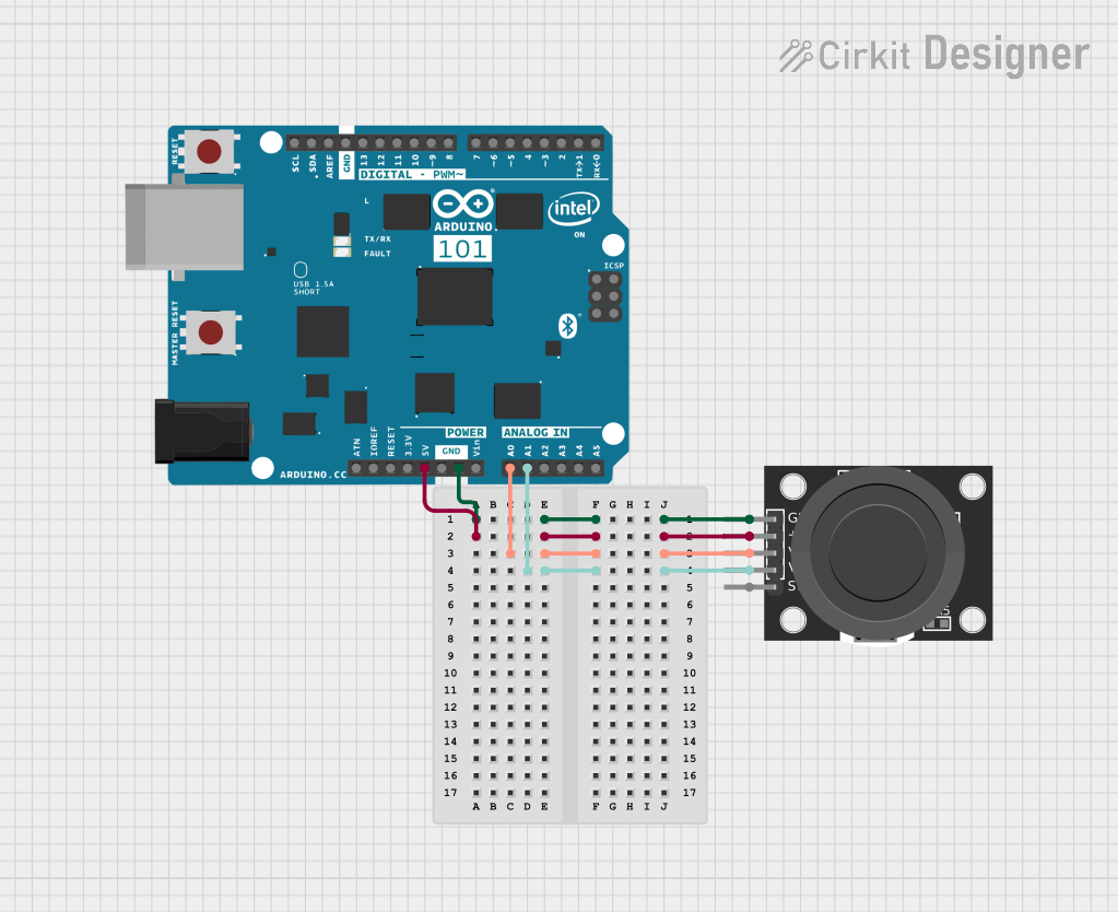 Open Project in Cirkit Designer
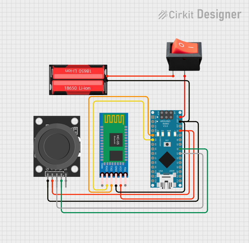 Open Project in Cirkit Designer
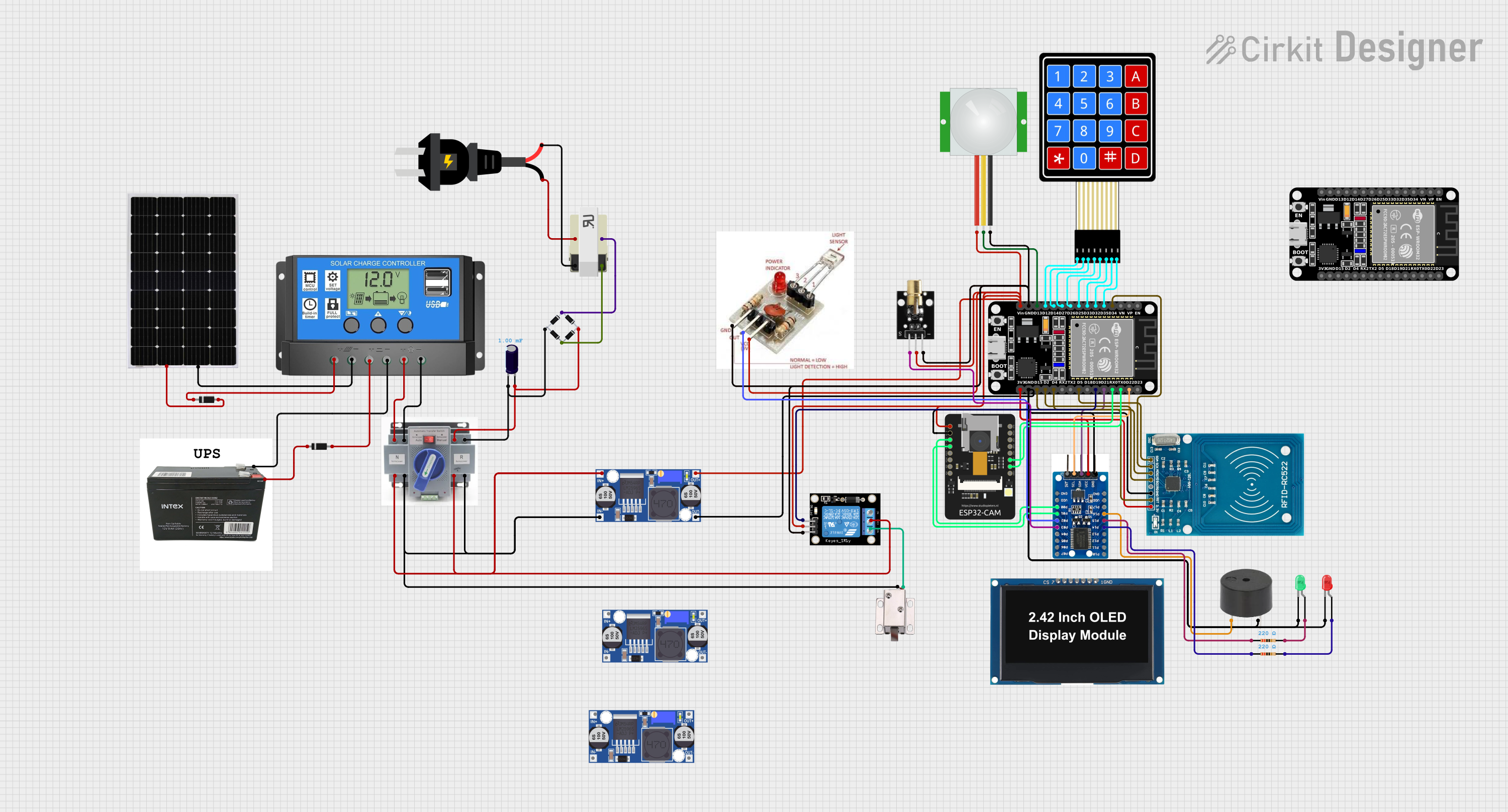 Open Project in Cirkit Designer
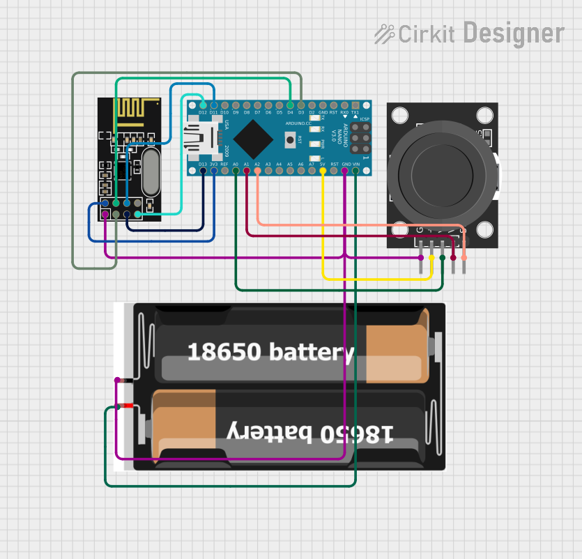 Open Project in Cirkit Designer
Explore Projects Built with KY-011
Open Project in Cirkit DesignerOpen Project in Cirkit DesignerOpen Project in Cirkit DesignerOpen Project in Cirkit DesignerCommon Applications and Use Cases
- Weather monitoring systems
- Home automation for climate control
- Greenhouse environmental monitoring
- Industrial humidity and temperature tracking
- IoT-based environmental sensing projects
Technical Specifications
The KY-011 module is built around the DHT11 sensor, which is known for its simplicity and efficiency. Below are the key technical details:
Key Specifications
| Parameter | Value |
|---|---|
| Operating Voltage | 3.3V to 5.5V |
| Operating Current | 0.3mA (measuring), 60µA (standby) |
| Temperature Range | 0°C to 50°C |
| Temperature Accuracy | ±2°C |
| Humidity Range | 20% to 90% RH |
| Humidity Accuracy | ±5% RH |
| Communication Protocol | Single-wire digital signal |
| Sampling Period | ≥1 second |
Pin Configuration
The KY-011 module has three pins for easy interfacing. Below is the pinout description:
| Pin Number | Pin Name | Description |
|---|---|---|
| 1 | VCC | Power supply input (3.3V to 5.5V) |
| 2 | DATA | Digital data output for temperature and humidity readings |
| 3 | GND | Ground connection |
Usage Instructions
The KY-011 module is straightforward to use in a circuit. Follow the steps below to integrate it into your project:
Connecting the KY-011 to an Arduino UNO
Wiring:
- Connect the
VCCpin of the KY-011 to the 5V pin on the Arduino UNO. - Connect the
GNDpin of the KY-011 to the GND pin on the Arduino UNO. - Connect the
DATApin of the KY-011 to a digital I/O pin on the Arduino UNO (e.g., pin 2).
- Connect the
Install Required Library:
- Download and install the
DHTlibrary from the Arduino Library Manager. This library simplifies communication with the DHT11 sensor.
- Download and install the
Arduino Code: Use the following example code to read temperature and humidity data from the KY-011 module:
// Include the DHT library for sensor communication
#include <DHT.h>

// Define the pin connected to the DATA pin of the KY-011
#define DHTPIN 2

// Define the sensor type (DHT11)
#define DHTTYPE DHT11

// Initialize the DHT sensor
DHT dht(DHTPIN, DHTTYPE);

void setup() {
  // Start the serial communication for debugging
  Serial.begin(9600);
  Serial.println("KY-011 Temperature and Humidity Sensor Test");

  // Initialize the DHT sensor
  dht.begin();
}

void loop() {
  // Wait a second between readings (DHT11 requires a 1-second delay)
  delay(1000);

  // Read humidity and temperature
  float humidity = dht.readHumidity();
  float temperature = dht.readTemperature();

  // Check if the readings are valid
  if (isnan(humidity) || isnan(temperature)) {
    Serial.println("Failed to read from DHT sensor!");
    return;
  }

  // Print the readings to the Serial Monitor
  Serial.print("Humidity: ");
  Serial.print(humidity);
  Serial.print(" %\t");
  Serial.print("Temperature: ");
  Serial.print(temperature);
  Serial.println(" °C");
}
Important Considerations and Best Practices
- Ensure the module is powered within its operating voltage range (3.3V to 5.5V).
- Avoid placing the sensor in environments with condensation or direct water exposure.
- Allow the sensor to stabilize for a few seconds after powering it on before taking readings.
- Use a pull-up resistor (typically 10kΩ) on the
DATAline if the module does not already include one.
Troubleshooting and FAQs
Common Issues and Solutions
No Data Output:
- Cause: Incorrect wiring or loose connections.
- Solution: Double-check the wiring and ensure all connections are secure.
Invalid or NaN Readings:
- Cause: Sensor not initialized properly or insufficient delay between readings.
- Solution: Ensure the
dht.begin()function is called in thesetup()and add a delay of at least 1 second between readings.
Inaccurate Readings:
- Cause: Sensor exposed to extreme conditions or interference.
- Solution: Place the sensor in a stable environment and avoid placing it near heat sources or high humidity areas.
Library Not Found:
- Cause: The required
DHTlibrary is not installed. - Solution: Install the library from the Arduino Library Manager.
- Cause: The required
FAQs
Q1: Can the KY-011 measure negative temperatures?
No, the DHT11 sensor used in the KY-011 module has a temperature range of 0°C to 50°C.
Q2: How often can I take readings from the KY-011?
The DHT11 sensor requires a minimum sampling period of 1 second between readings.
Q3: Can I use the KY-011 with a 3.3V microcontroller?
Yes, the KY-011 operates within a voltage range of 3.3V to 5.5V, making it compatible with 3.3V systems.
Q4: Is the KY-011 suitable for outdoor use?
The KY-011 is not waterproof and should be protected from direct exposure to water or condensation when used outdoors.