
How to Use JUMPER-3: Examples, Pinouts, and Specs
 Design with JUMPER-3 in Cirkit Designer
Introduction
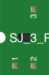
The JUMPER-3 is a small, versatile connector used to close or complete an electrical circuit. It typically consists of three pins arranged in a row, allowing users to modify circuit behavior by connecting specific pins. By placing a removable shunt (a small conductive sleeve) over two adjacent pins, the circuit can be configured in different ways. This component is widely used in electronics for setting hardware configurations, enabling or disabling features, and selecting between multiple operational modes.
Explore Projects Built with JUMPER-3
 Open Project in Cirkit Designer
 Open Project in Cirkit Designer
 Open Project in Cirkit Designer
 Open Project in Cirkit Designer
Explore Projects Built with JUMPER-3
Open Project in Cirkit DesignerOpen Project in Cirkit DesignerOpen Project in Cirkit DesignerOpen Project in Cirkit DesignerCommon Applications and Use Cases
- Configuring hardware settings on motherboards, development boards, and other devices.
- Selecting between different voltage levels or operational modes in circuits.
- Enabling or disabling specific features in embedded systems.
- Debugging and testing circuits by temporarily modifying connections.
Technical Specifications
The JUMPER-3 is a passive component with no active electrical properties. Its specifications are primarily mechanical and depend on the materials and dimensions of the pins and shunt.
Key Technical Details
- Number of Pins: 3
- Pin Spacing (Pitch): 2.54 mm (standard for most PCBs)
- Maximum Current Rating: 2 A (varies by manufacturer)
- Maximum Voltage Rating: 50 V DC
- Shunt Material: Conductive metal with plastic insulation
- Durability: Rated for 200+ insertion/removal cycles
Pin Configuration and Descriptions
The JUMPER-3 consists of three pins, labeled as follows:
| Pin Number | Label | Description |
|---|---|---|
| 1 | VCC | Typically connected to a voltage source. |
| 2 | MID | Middle pin, used for configuration purposes. |
| 3 | GND | Typically connected to ground. |
The configuration depends on which two pins are connected by the shunt:
- Pins 1 and 2 connected: Enables one mode or feature.
- Pins 2 and 3 connected: Enables an alternate mode or feature.
- No connection: Disables the feature or leaves the circuit open.
Usage Instructions
How to Use the JUMPER-3 in a Circuit
- Identify the Pins: Refer to the circuit schematic or PCB silkscreen to locate the JUMPER-3 and understand its function in the circuit.
- Select the Desired Configuration: Determine which two pins need to be connected to achieve the desired behavior.
- Place the Shunt: Carefully place the shunt over the two selected pins. Ensure it is seated firmly to maintain a reliable connection.
- Test the Circuit: Power on the circuit and verify that the desired configuration is active.
Important Considerations and Best Practices
- Avoid Overcurrent: Ensure the current through the JUMPER-3 does not exceed its maximum rating (2 A).
- Handle with Care: Repeated insertion and removal of the shunt can wear out the pins or shunt. Use gentle force to avoid damage.
- Prevent Short Circuits: Ensure the shunt does not accidentally connect unintended pins or components.
- Use Proper Tools: If the shunt is difficult to remove, use tweezers or a small tool to avoid damaging the component.
Example: Using JUMPER-3 with an Arduino UNO
The JUMPER-3 can be used to select between two operational modes in an Arduino-based project. For example, it can toggle between two input pins for a sensor.
Circuit Setup
- Connect Pin 1 of the JUMPER-3 to Arduino digital pin 2.
- Connect Pin 2 to Arduino digital pin 3.
- Connect Pin 3 to GND.
Arduino Code
// Example code for using JUMPER-3 to toggle between two modes
const int pin1 = 2; // Pin connected to JUMPER-3 Pin 1
const int pin2 = 3; // Pin connected to JUMPER-3 Pin 2

void setup() {
  pinMode(pin1, INPUT_PULLUP); // Configure pin1 as input with pull-up resistor
  pinMode(pin2, INPUT_PULLUP); // Configure pin2 as input with pull-up resistor
  Serial.begin(9600);          // Initialize serial communication
}

void loop() {
  if (digitalRead(pin1) == LOW) {
    // If JUMPER-3 connects Pin 1 and Pin 2, Mode 1 is active
    Serial.println("Mode 1 Active");
  } else if (digitalRead(pin2) == LOW) {
    // If JUMPER-3 connects Pin 2 and Pin 3, Mode 2 is active
    Serial.println("Mode 2 Active");
  } else {
    // If no connection, no mode is active
    Serial.println("No Mode Active");
  }
  delay(500); // Delay for readability
}
Troubleshooting and FAQs
Common Issues
Shunt Does Not Fit Properly:
- Ensure the shunt matches the pin spacing (2.54 mm pitch).
- Check for bent or damaged pins and straighten them carefully.
Circuit Does Not Respond to Configuration Changes:
- Verify the shunt is placed correctly over the intended pins.
- Check for loose connections or damaged shunt material.
Short Circuit Detected:
- Ensure the shunt is not accidentally connecting unintended pins.
- Inspect the PCB for solder bridges or other conductive debris.
FAQs
Q: Can I use the JUMPER-3 for high-current applications?
A: No, the JUMPER-3 is typically rated for a maximum current of 2 A. For higher currents, use a more robust connector.
Q: How do I know which pins to connect?
A: Refer to the circuit schematic or device manual. The function of each pin is usually labeled on the PCB.
Q: Can I use the JUMPER-3 without a shunt?
A: Without a shunt, the JUMPER-3 will leave the circuit open, effectively disabling the feature or mode it controls.
Q: How durable is the JUMPER-3?
A: The JUMPER-3 is rated for approximately 200+ insertion/removal cycles, depending on the quality of the component.