How to Use Pololu S9V11F3S5C3 Buck-Boost (#2873): Examples, Pinouts, and Specs
Introduction
The Pololu S9V11F3S5C3 is a compact and efficient buck-boost voltage regulator designed to provide a stable output voltage of 3.3V or 5V from a wide input voltage range of 2V to 16V. This versatile component is ideal for applications where the input voltage can vary above or below the desired output voltage, such as battery-powered devices, portable electronics, and embedded systems.
Explore Projects Built with Pololu S9V11F3S5C3 Buck-Boost (#2873)


Explore Projects Built with Pololu S9V11F3S5C3 Buck-Boost (#2873)
Common Applications
- Powering microcontrollers and sensors in embedded systems
- Battery-powered devices with fluctuating input voltage
- Portable electronics requiring a stable voltage supply
- Robotics and automation systems
- Prototyping and development projects
Technical Specifications
Key Specifications
| Parameter | Value |
|---|---|
| Manufacturer | Pololu |
| Part Number | S9V11F3S5C3 |
| Input Voltage Range | 2V to 16V |
| Output Voltage Options | 3.3V or 5V (selectable) |
| Maximum Output Current | 1.5A (depending on input/output conditions) |
| Efficiency | Up to 90% |
| Dimensions | 0.6" × 0.8" × 0.1" (15 × 20 × 3 mm) |
| Weight | 0.6 g |
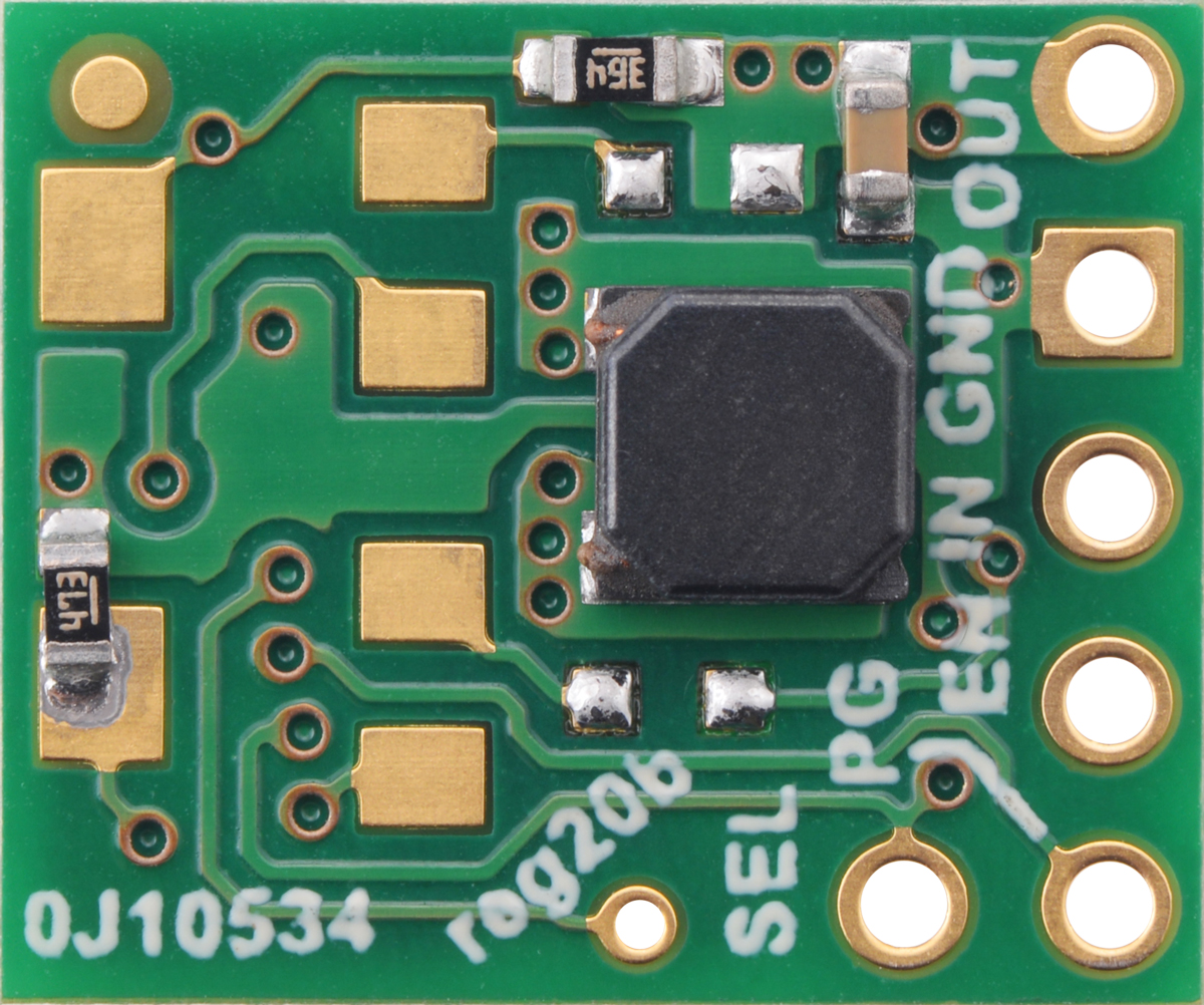
Pin Configuration and Descriptions
The Pololu S9V11F3S5C3 has six pins, as described in the table below:
| Pin Name | Pin Number | Description |
|---|---|---|
| VIN | 1 | Input voltage pin (2V to 16V). Connect to the positive terminal of the power source. |
| GND | 2 | Ground pin. Connect to the negative terminal of the power source. |
| VOUT | 3 | Regulated output voltage pin (3.3V or 5V). Connect to the load. |
| SHDN | 4 | Shutdown pin. Drive low to disable the regulator; leave floating or drive high to enable. |
| SEL | 5 | Voltage selection pin. Drive low for 3.3V output or high for 5V output. |
| PG | 6 | Power good indicator pin. Outputs high when the output voltage is stable. |
Usage Instructions
How to Use the Component in a Circuit
- Power Input: Connect the VIN pin to a power source within the 2V to 16V range. Ensure the power source can supply sufficient current for your application.
- Ground Connection: Connect the GND pin to the ground of your circuit.
- Output Voltage Selection: Use the SEL pin to select the desired output voltage:
- Drive SEL low for a 3.3V output.
- Drive SEL high for a 5V output.
- Load Connection: Connect the VOUT pin to the load that requires a stable voltage.
- Enable/Disable: Use the SHDN pin to enable or disable the regulator:
- Drive SHDN high or leave it floating to enable the regulator.
- Drive SHDN low to disable the regulator.
- Power Good Monitoring: Optionally, connect the PG pin to monitor the output voltage status. The PG pin will output high when the output voltage is stable.
Important Considerations and Best Practices
- Input Voltage Range: Ensure the input voltage stays within the specified range (2V to 16V) to avoid damaging the regulator.
- Output Current: The maximum output current depends on the input voltage and output voltage. Refer to the efficiency curves in the datasheet for detailed information.
- Heat Dissipation: Although the regulator is efficient, it may generate heat under high load conditions. Ensure adequate ventilation or heat sinking if necessary.
- Bypass Capacitors: Add appropriate bypass capacitors near the VIN and VOUT pins to reduce noise and improve stability.
Example: Using with an Arduino UNO
The Pololu S9V11F3S5C3 can be used to power an Arduino UNO from a battery or other variable voltage source. Below is an example circuit and Arduino code to monitor the PG pin.
Circuit Connections
- Connect the VIN pin to the positive terminal of a 9V battery.
- Connect the GND pin to the negative terminal of the battery and the Arduino GND.
- Connect the VOUT pin to the Arduino's 5V pin.
- Connect the PG pin to Arduino digital pin 2.
Arduino Code
const int pgPin = 2; // Power Good pin connected to digital pin 2

void setup() {
  pinMode(pgPin, INPUT); // Set PG pin as input
  Serial.begin(9600);    // Initialize serial communication
}

void loop() {
  int pgStatus = digitalRead(pgPin); // Read the PG pin status

  if (pgStatus == HIGH) {
    Serial.println("Output voltage is stable."); // PG pin is high when voltage is stable
  } else {
    Serial.println("Output voltage is unstable!"); // PG pin is low if voltage is not stable
  }

  delay(1000); // Wait for 1 second before checking again
}
Troubleshooting and FAQs
Common Issues and Solutions
No Output Voltage
- Cause: SHDN pin is driven low.
- Solution: Ensure the SHDN pin is left floating or driven high to enable the regulator.
Output Voltage is Incorrect
- Cause: SEL pin is not configured correctly.
- Solution: Verify the SEL pin is driven low for 3.3V output or high for 5V output.
Regulator Overheating
- Cause: Excessive load current or insufficient ventilation.
- Solution: Reduce the load current or improve heat dissipation with proper airflow or heat sinking.
PG Pin Always Low
- Cause: Output voltage is not stable or load exceeds the regulator's capacity.
- Solution: Check the input voltage and ensure the load is within the regulator's specifications.
FAQs
Q: Can I use this regulator to power a Raspberry Pi?
A: Yes, but ensure the input voltage and current requirements of the Raspberry Pi are met. The regulator can provide up to 1.5A, which is sufficient for most Raspberry Pi models under normal conditions.
Q: What happens if the input voltage drops below 2V?
A: The regulator will stop functioning, and the output voltage will drop. Ensure the input voltage stays within the specified range.
Q: Can I leave the SEL pin floating?
A: No, the SEL pin must be explicitly driven high or low to select the output voltage.
Q: Is reverse polarity protection included?
A: No, the regulator does not have built-in reverse polarity protection. Use a diode or other protection circuit to prevent damage.