How to Use Slip Ring: Examples, Pinouts, and Specs

Introduction
A slip ring is an electromechanical device designed to enable the transmission of power, electrical signals, or data between a stationary structure and a rotating one. It is a critical component in systems where continuous rotation is required without interrupting the electrical connection. Slip rings are commonly used in wind turbines, rotating machinery, robotics, medical imaging equipment, and industrial automation systems.
By eliminating the need for fixed wiring in rotating systems, slip rings enhance mechanical performance, simplify system design, and reduce wear and tear caused by repeated cable flexing.
Explore Projects Built with Slip Ring


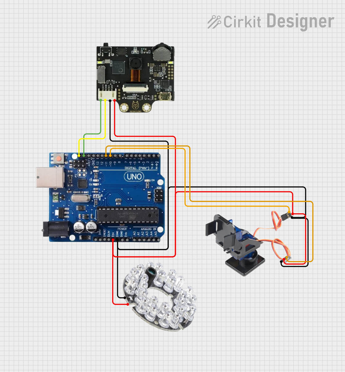
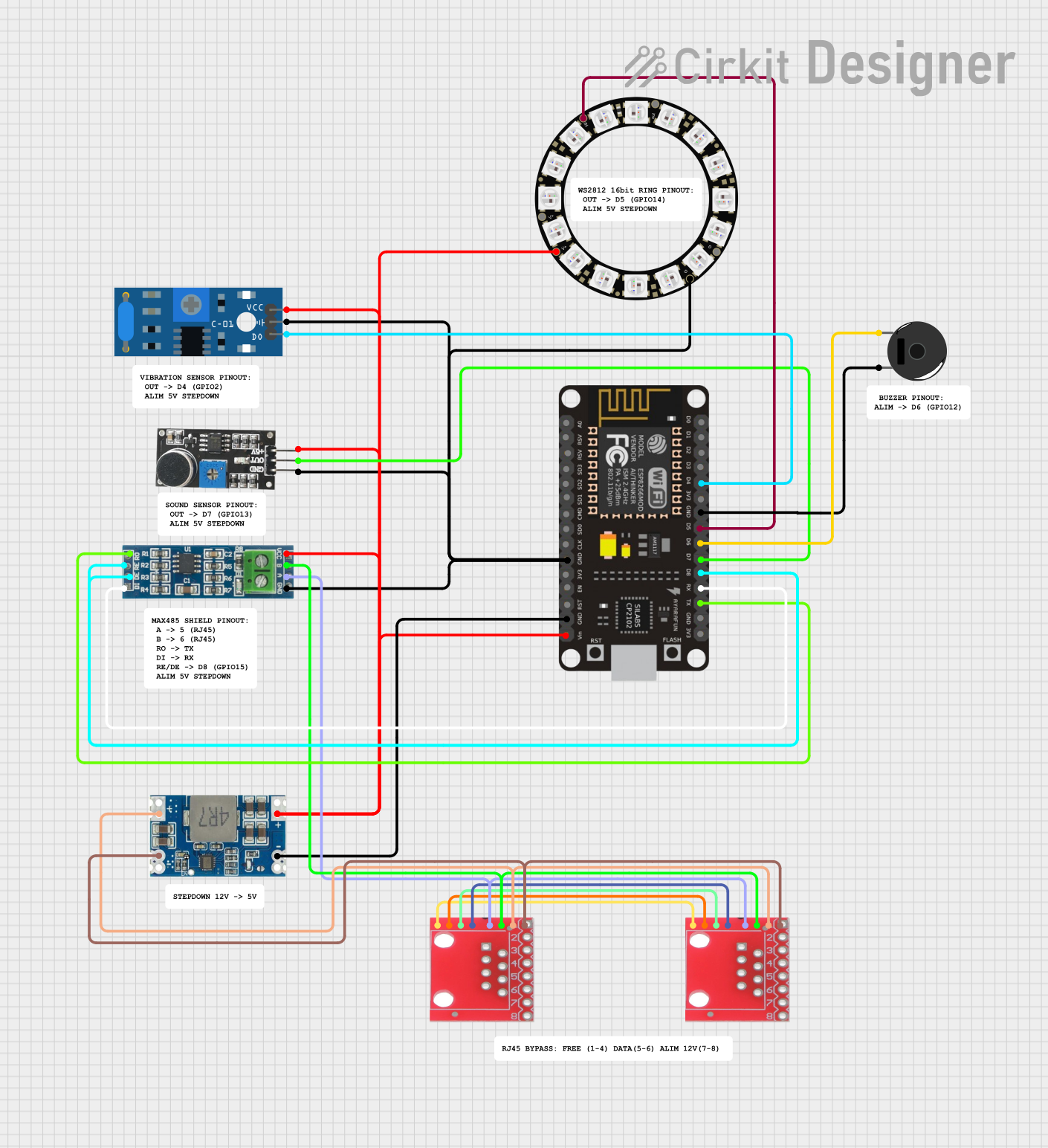
Explore Projects Built with Slip Ring
Technical Specifications
Below are the general technical specifications for a typical slip ring. Note that specific models may vary, so always refer to the datasheet of the particular slip ring you are using.
General Specifications
- Voltage Rating: 240V AC/DC (typical, varies by model)
- Current Rating: 2A to 30A per circuit (depending on the model)
- Number of Circuits: 2 to 50 (or more, depending on the application)
- Rotational Speed: Up to 300 RPM (higher speeds available for specialized models)
- Contact Material: Gold, silver, or copper alloy (varies by design)
- Insulation Resistance: ≥ 100 MΩ @ 500V DC
- Operating Temperature: -40°C to +80°C
- Housing Material: Aluminum alloy or plastic (depending on the application)
Pin Configuration and Descriptions
The pin configuration of a slip ring depends on the number of circuits it supports. Below is an example of a 6-circuit slip ring:
| Pin Number | Description | Wire Color (Typical) |
|---|---|---|
| 1 | Power Line 1 (Positive) | Red |
| 2 | Power Line 1 (Negative) | Black |
| 3 | Signal Line 1 | Yellow |
| 4 | Signal Line 2 | Green |
| 5 | Ground | Blue |
| 6 | Shielding or Additional Signal | White |
Always refer to the manufacturer's datasheet for the exact pinout and wire color coding.
Usage Instructions
How to Use the Slip Ring in a Circuit
- Identify the Connections: Refer to the pin configuration table or the datasheet to identify the power, signal, and ground connections.
- Mount the Slip Ring: Secure the stationary part of the slip ring to the fixed structure and the rotating part to the rotating structure. Ensure proper alignment to avoid mechanical stress.
- Connect the Wires: Solder or crimp the wires to the corresponding terminals in your circuit. Use heat shrink tubing or insulation tape to prevent short circuits.
- Test the Connections: Before powering the system, use a multimeter to verify continuity and ensure there are no short circuits.
- Power On: Once all connections are verified, power on the system and test the slip ring's performance under rotation.
Important Considerations and Best Practices
- Avoid Overloading: Ensure the current and voltage do not exceed the slip ring's rated capacity.
- Minimize Friction: Use a slip ring with high-quality contact materials to reduce wear and extend its lifespan.
- Protect from Dust and Moisture: If the slip ring is used in harsh environments, consider using a sealed or IP-rated model.
- Cable Management: Secure the wires to prevent tangling or excessive strain during rotation.
- Regular Maintenance: Periodically inspect the slip ring for wear, debris, or damage to ensure reliable operation.
Example: Using a Slip Ring with an Arduino UNO
Below is an example of how to use a slip ring to transmit a signal from a rotating sensor to an Arduino UNO:
/*
  Example: Reading a signal from a rotating potentiometer via a slip ring
  connected to an Arduino UNO.

  Pin Configuration:
  - Slip ring wire 1 (Red): 5V
  - Slip ring wire 2 (Black): GND
  - Slip ring wire 3 (Yellow): Signal from potentiometer
*/

const int potPin = A0; // Analog pin connected to the potentiometer signal
int potValue = 0;      // Variable to store the potentiometer value

void setup() {
  Serial.begin(9600); // Initialize serial communication at 9600 baud
}

void loop() {
  potValue = analogRead(potPin); // Read the potentiometer value
  Serial.print("Potentiometer Value: ");
  Serial.println(potValue); // Print the value to the Serial Monitor
  delay(500); // Wait for 500ms before the next reading
}
Troubleshooting and FAQs
Common Issues and Solutions
Intermittent Signal Transmission
- Cause: Worn-out contacts or debris inside the slip ring.
- Solution: Clean the slip ring contacts or replace the unit if necessary.
Excessive Heat Generation
- Cause: Overloading the slip ring beyond its rated current.
- Solution: Reduce the load or use a slip ring with a higher current rating.
Noise in Signal Transmission
- Cause: Poor contact material or high rotational speed.
- Solution: Use a slip ring with gold-plated contacts for better conductivity and reduce the rotational speed.
Mechanical Failure
- Cause: Misalignment or excessive mechanical stress.
- Solution: Ensure proper alignment during installation and avoid over-tightening the mounting hardware.
FAQs
Q1: Can a slip ring transmit both power and data simultaneously?
A1: Yes, many slip rings are designed to handle both power and data transmission. Ensure the slip ring is rated for the specific data protocol (e.g., Ethernet, USB) if required.
Q2: How do I choose the right slip ring for my application?
A2: Consider the number of circuits, voltage and current ratings, rotational speed, and environmental conditions (e.g., dust, moisture) when selecting a slip ring.
Q3: Can slip rings be used for high-speed applications?
A3: Yes, but you must select a slip ring specifically designed for high-speed operation to ensure reliable performance and durability.
Q4: Are slip rings maintenance-free?
A4: Some slip rings are designed to be maintenance-free, but regular inspection and cleaning are recommended for optimal performance in most cases.