How to Use TTF Round Display: Examples, Pinouts, and Specs
Introduction
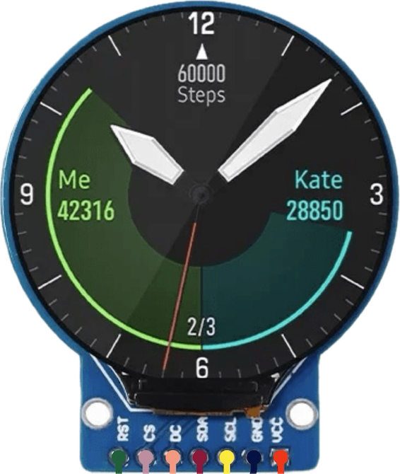
The TTF Round Display (Part ID: TTF001) is a circular graphical display designed for applications requiring a visually appealing and compact interface. Its round shape makes it ideal for use in digital clocks, smartwatches, automotive dashboards, gauges, and other devices where a circular display enhances the user experience. The display typically employs LED or LCD technology to deliver clear and vibrant visuals.
This component is versatile and can be integrated into a variety of projects, ranging from hobbyist electronics to professional-grade devices.
Explore Projects Built with TTF Round Display
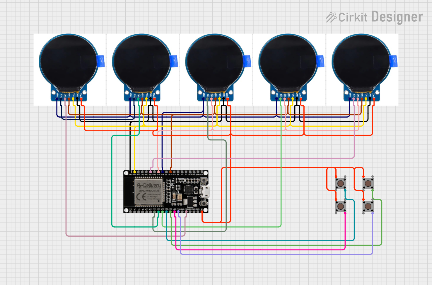
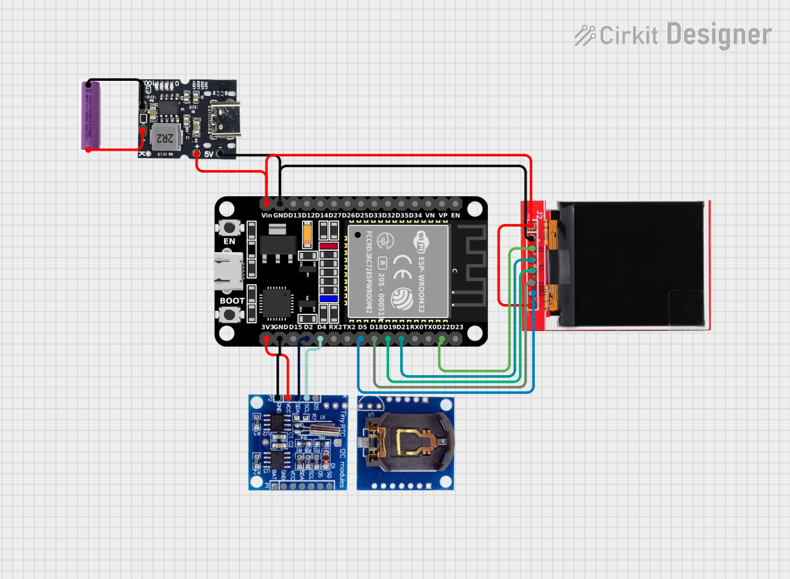
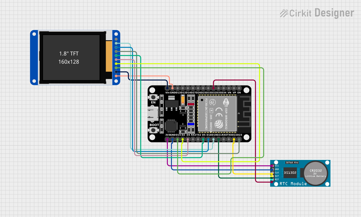

Explore Projects Built with TTF Round Display
Technical Specifications
Below are the key technical details for the TTF Round Display:
| Parameter | Value |
|---|---|
| Display Type | LED/LCD (varies by model) |
| Shape | Round |
| Resolution | 240 x 240 pixels |
| Interface | SPI (Serial Peripheral Interface) |
| Operating Voltage | 3.3V |
| Current Consumption | ~20mA (typical) |
| Backlight | LED |
| Viewing Angle | 160° |
| Operating Temperature | -20°C to 70°C |
| Dimensions | 1.28 inches (diameter) |
Pin Configuration
The TTF Round Display typically features an 8-pin interface. Below is the pinout description:
| Pin | Name | Description |
|---|---|---|
| 1 | VCC | Power supply (3.3V) |
| 2 | GND | Ground |
| 3 | SCL | Serial Clock (SPI clock input) |
| 4 | SDA | Serial Data (SPI data input) |
| 5 | RES | Reset pin (active low) |
| 6 | DC | Data/Command control pin |
| 7 | CS | Chip Select (active low) |
| 8 | BL | Backlight control (PWM or ON/OFF) |
Usage Instructions
How to Use the TTF Round Display in a Circuit
- Power Supply: Connect the VCC pin to a 3.3V power source and the GND pin to ground.
- SPI Interface: Use the SCL and SDA pins to communicate with the display via an SPI-compatible microcontroller (e.g., Arduino UNO).
- Control Pins:
- Connect the RES pin to a GPIO pin on the microcontroller for resetting the display.
- Use the DC pin to toggle between data and command modes.
- The CS pin should be connected to a GPIO pin to enable or disable the display.
- Backlight: The BL pin can be connected to a PWM-capable GPIO pin for brightness control or directly to VCC for constant backlight.
Important Considerations and Best Practices
- Voltage Levels: Ensure the microcontroller's logic levels are compatible with the display's 3.3V interface. Use a level shifter if necessary.
- Initialization: The display requires proper initialization commands to function. Refer to the datasheet or library documentation for the correct sequence.
- Backlight Control: Use PWM to adjust the brightness and reduce power consumption.
- Avoid Overheating: Operate the display within the specified temperature range to prevent damage.
Example Code for Arduino UNO
Below is an example of how to interface the TTF Round Display with an Arduino UNO using the SPI protocol:
#include <SPI.h>

// Define pin connections
#define CS_PIN 10    // Chip Select
#define DC_PIN 9     // Data/Command
#define RES_PIN 8    // Reset

void setup() {
  // Initialize SPI communication
  SPI.begin();

  // Set pin modes
  pinMode(CS_PIN, OUTPUT);
  pinMode(DC_PIN, OUTPUT);
  pinMode(RES_PIN, OUTPUT);

  // Reset the display
  digitalWrite(RES_PIN, LOW);  // Pull reset pin low
  delay(10);                   // Wait for 10ms
  digitalWrite(RES_PIN, HIGH); // Release reset pin
  delay(10);                   // Wait for 10ms

  // Initialize the display (example command sequence)
  digitalWrite(CS_PIN, LOW);   // Select the display
  sendCommand(0x01);           // Software reset command
  delay(120);                  // Wait for reset to complete
  sendCommand(0x11);           // Exit sleep mode
  delay(120);                  // Wait for the display to wake up
  digitalWrite(CS_PIN, HIGH);  // Deselect the display
}

void loop() {
  // Example: Display content can be updated here
}

// Function to send a command to the display
void sendCommand(uint8_t cmd) {
  digitalWrite(DC_PIN, LOW);   // Set to command mode
  SPI.transfer(cmd);           // Send command via SPI
}

// Function to send data to the display
void sendData(uint8_t data) {
  digitalWrite(DC_PIN, HIGH);  // Set to data mode
  SPI.transfer(data);          // Send data via SPI
}
Troubleshooting and FAQs
Common Issues and Solutions
Display Not Turning On:
- Verify the power supply connections (VCC and GND).
- Ensure the backlight (BL) pin is connected properly.
No Output on the Display:
- Check the SPI connections (SCL, SDA, CS, DC).
- Confirm that the initialization sequence is correct.
Flickering or Dim Backlight:
- Ensure the backlight pin (BL) is receiving a stable voltage or PWM signal.
- Check for loose connections.
Display Freezes or Becomes Unresponsive:
- Reset the display using the RES pin.
- Verify that the SPI clock speed is within the display's supported range.
FAQs
Q: Can I use the TTF Round Display with a 5V microcontroller?
A: Yes, but you will need a level shifter to convert the 5V logic signals to 3.3V.
Q: Is there a library available for this display?
A: While there may not be an official library, many generic SPI display libraries (e.g., Adafruit GFX) can be adapted for use with this display.
Q: How do I control the brightness of the backlight?
A: Connect the BL pin to a PWM-capable GPIO pin on your microcontroller and adjust the duty cycle to control brightness.
Q: Can I daisy-chain multiple displays?
A: No, the TTF Round Display does not support daisy-chaining. Each display requires a separate SPI connection.