
How to Use D2523T: Examples, Pinouts, and Specs
 Design with D2523T in Cirkit Designer
Introduction
The D2523T is a high-performance N-channel MOSFET designed for efficient switching applications. It features low on-resistance and fast switching speeds, making it ideal for use in power management, motor control, and amplification circuits. Its robust design ensures reliable operation in a wide range of electronic applications, from consumer electronics to industrial systems.
Explore Projects Built with D2523T
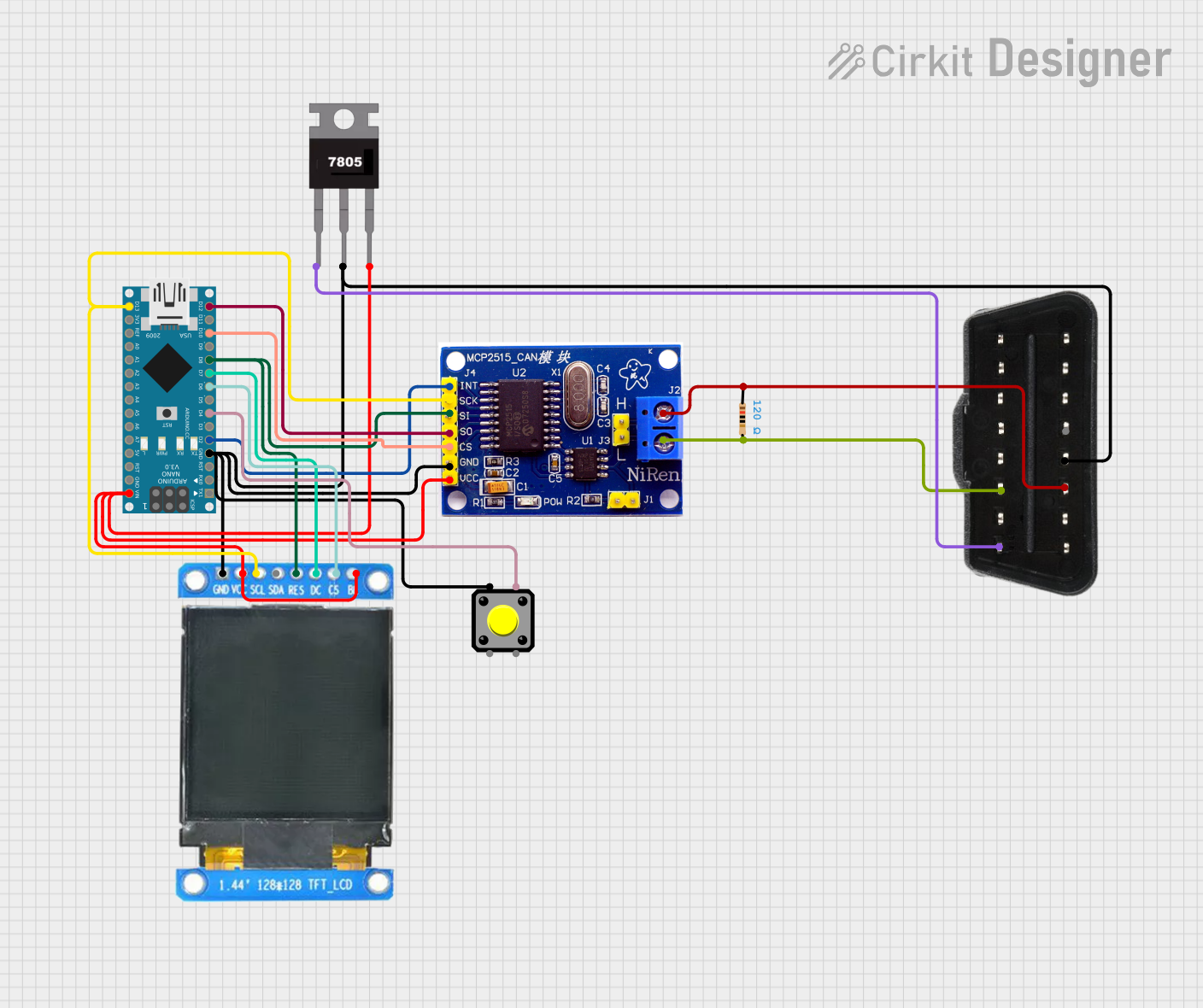 Open Project in Cirkit Designer
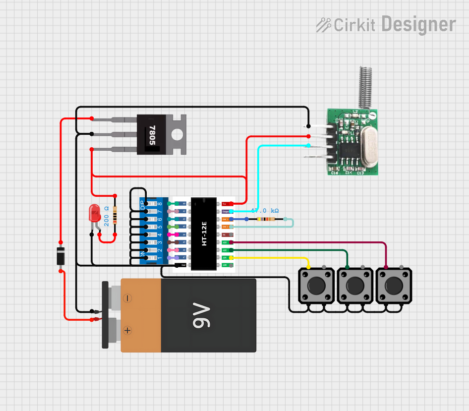 Open Project in Cirkit Designer
 Open Project in Cirkit Designer
 Open Project in Cirkit Designer
Explore Projects Built with D2523T
Open Project in Cirkit DesignerOpen Project in Cirkit DesignerOpen Project in Cirkit DesignerOpen Project in Cirkit DesignerCommon Applications:
- Power management in DC-DC converters
- Motor drivers and control circuits
- Amplification in audio and RF systems
- Switching in high-speed digital circuits
- Battery-powered devices for energy efficiency
Technical Specifications
Key Technical Details:
| Parameter | Value |
|---|---|
| Type | N-Channel MOSFET |
| Maximum Drain-Source Voltage (VDS) | 100V |
| Maximum Gate-Source Voltage (VGS) | ±20V |
| Continuous Drain Current (ID) | 25A |
| Pulsed Drain Current (IDM) | 100A |
| On-Resistance (RDS(on)) | 0.05Ω |
| Power Dissipation (PD) | 50W |
| Operating Temperature Range | -55°C to +150°C |
| Package Type | TO-220 |
Pin Configuration:
The D2523T MOSFET is typically housed in a TO-220 package with three pins. The pinout is as follows:
| Pin Number | Name | Description |
|---|---|---|
| 1 | Gate | Controls the MOSFET switching state |
| 2 | Drain | Current flows from drain to source |
| 3 | Source | Connected to ground or load return |
Usage Instructions
How to Use the D2523T in a Circuit:
- Gate Control: Apply a voltage to the Gate (Pin 1) to control the MOSFET's switching state. Ensure the gate voltage (VGS) is within the specified range (±20V).
- Drain-Source Connection: Connect the load between the Drain (Pin 2) and the positive supply voltage. The Source (Pin 3) is typically connected to ground.
- Gate Resistor: Use a resistor (typically 10Ω to 100Ω) in series with the Gate to limit inrush current and prevent damage to the MOSFET.
- Flyback Diode: For inductive loads (e.g., motors), include a flyback diode across the load to protect the MOSFET from voltage spikes during switching.
Example Circuit:
Below is an example of using the D2523T to control a DC motor with an Arduino UNO:
Circuit Diagram:
- Gate (Pin 1): Connected to Arduino digital pin (e.g., D9) through a 100Ω resistor.
- Drain (Pin 2): Connected to one terminal of the motor.
- Source (Pin 3): Connected to ground.
- Flyback Diode: Connected across the motor terminals.
Arduino Code:
// Example code to control a motor using the D2523T MOSFET and Arduino UNO

const int motorPin = 9; // Pin connected to the Gate of the MOSFET

void setup() {
  pinMode(motorPin, OUTPUT); // Set the motor pin as an output
}

void loop() {
  analogWrite(motorPin, 128); // Set motor speed to 50% (PWM value: 128)
  delay(5000);               // Run motor for 5 seconds

  analogWrite(motorPin, 0);  // Turn off the motor
  delay(5000);               // Wait for 5 seconds
}
Important Considerations:
- Heat Dissipation: Ensure proper heat sinking for the MOSFET, as it can dissipate significant power during operation.
- Gate Drive Voltage: Use a gate drive voltage of at least 10V for optimal performance.
- Switching Speed: Minimize parasitic capacitance and inductance in the circuit to achieve fast switching speeds.
Troubleshooting and FAQs
Common Issues:
MOSFET Overheating:
- Cause: Insufficient heat sinking or excessive current.
- Solution: Attach an appropriate heatsink to the MOSFET and ensure the current is within the specified limits.
MOSFET Not Switching:
- Cause: Insufficient gate voltage or incorrect wiring.
- Solution: Verify that the gate voltage is at least 10V and check the circuit connections.
Voltage Spikes Damaging the MOSFET:
- Cause: Inductive loads generating back EMF.
- Solution: Add a flyback diode across the load to suppress voltage spikes.
Low Efficiency:
- Cause: High on-resistance or poor gate drive.
- Solution: Ensure the gate drive voltage is sufficient and minimize resistance in the circuit.
FAQs:
Q1: Can the D2523T be used for high-frequency switching?
A1: Yes, the D2523T is suitable for high-frequency switching applications due to its fast switching speeds. However, ensure proper circuit design to minimize parasitic effects.
Q2: What is the maximum current the D2523T can handle?
A2: The D2523T can handle a continuous drain current of 25A and a pulsed drain current of up to 100A.
Q3: Do I need a gate driver for the D2523T?
A3: A gate driver is recommended for high-speed or high-power applications to ensure proper gate voltage levels and fast switching.
Q4: Can I use the D2523T with a 3.3V microcontroller?
A4: The D2523T requires a gate voltage of at least 10V for optimal performance. Use a level shifter or gate driver to interface with a 3.3V microcontroller.