How to Use INMP441: Examples, Pinouts, and Specs
Introduction
The INMP441 is a low-power, high-performance MEMS (Micro-Electro-Mechanical Systems) microphone manufactured by Analog Devices (MIC). It features a digital I2S (Inter-IC Sound) interface, enabling direct connection to digital audio processors, microcontrollers, and DSPs without the need for an external ADC. The INMP441 is designed for applications requiring high-quality audio capture, such as portable devices, voice recognition systems, and audio processing applications.
Explore Projects Built with INMP441
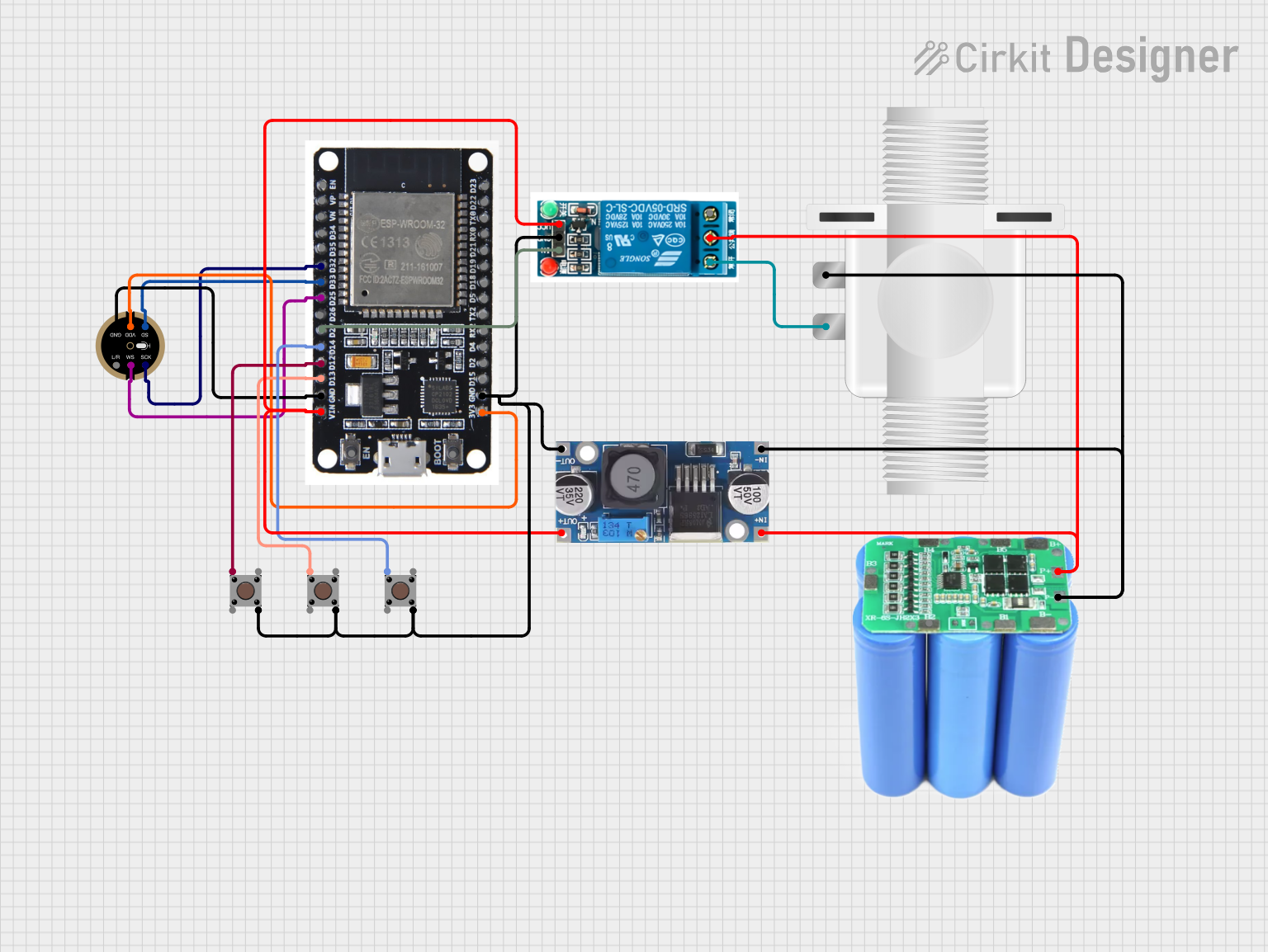
Explore Projects Built with INMP441
Common Applications:
- Voice recognition systems (e.g., smart assistants)
- Audio recording and processing
- Portable devices (e.g., smartphones, tablets)
- IoT devices with audio input
- Noise-canceling systems
Technical Specifications
The INMP441 is designed to deliver high performance while maintaining low power consumption. Below are its key technical specifications:
| Parameter | Value |
|---|---|
| Supply Voltage (VDD) | 1.8V to 3.3V |
| Current Consumption | 1.4 mA (typical) |
| Signal-to-Noise Ratio (SNR) | 61 dB |
| Acoustic Overload Point | 120 dB SPL |
| Frequency Response | 60 Hz to 15 kHz |
| Sensitivity | -26 dBFS ±1 dB |
| Output Format | I2S (Pulse Density Modulation) |
| Operating Temperature Range | -40°C to +85°C |
| Dimensions | 3.5 mm × 2.65 mm × 0.98 mm |
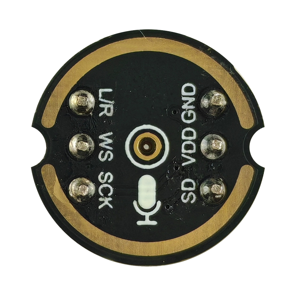
Pin Configuration and Descriptions
The INMP441 has a total of 7 pins. Below is the pinout and description:
| Pin Name | Pin Number | Description |
|---|---|---|
| VDD | 1 | Power supply input (1.8V to 3.3V). |
| GND | 2 | Ground connection. |
| WS | 3 | Word Select (I2S clock signal for left/right channel selection). |
| SCK | 4 | Serial Clock (I2S clock signal for data synchronization). |
| SD | 5 | Serial Data (I2S data output). |
| L/R | 6 | Left/Right channel select. Connect to GND for left channel or VDD for right. |
| NC | 7 | No connection. Leave unconnected or grounded. |
Usage Instructions
Connecting the INMP441 to a Microcontroller
The INMP441 communicates using the I2S protocol, which requires three main signals: SCK (Serial Clock), WS (Word Select), and SD (Serial Data). Below are the steps to use the INMP441 in a circuit:
- Power Supply: Connect the
VDDpin to a 1.8V–3.3V power source and theGNDpin to ground. - I2S Interface:
- Connect the
SCKpin to the I2S clock pin of the microcontroller. - Connect the
WSpin to the I2S word select pin of the microcontroller. - Connect the
SDpin to the I2S data input pin of the microcontroller.
- Connect the
- Channel Selection:
- Connect the
L/Rpin toGNDfor the left audio channel or toVDDfor the right audio channel.
- Connect the
- No Connection Pin: Leave the
NCpin unconnected or connect it to ground.
Important Considerations:
- Ensure the microcontroller supports I2S communication.
- Use decoupling capacitors (e.g., 0.1 µF) near the
VDDpin to reduce noise. - Avoid long wires for I2S signals to minimize signal degradation.
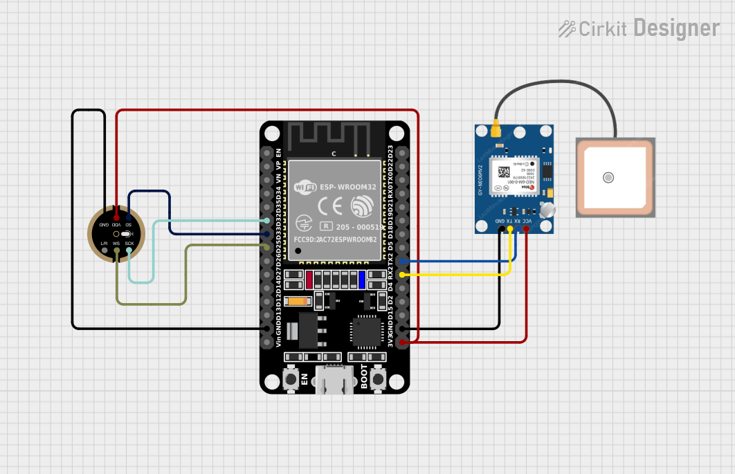
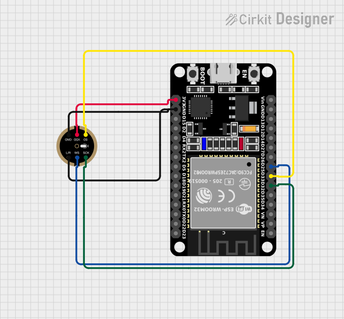
Example: Using INMP441 with Arduino UNO
The Arduino UNO does not natively support I2S communication. However, you can use an external I2S interface module or switch to a microcontroller like the ESP32, which has built-in I2S support. Below is an example of using the INMP441 with an ESP32:
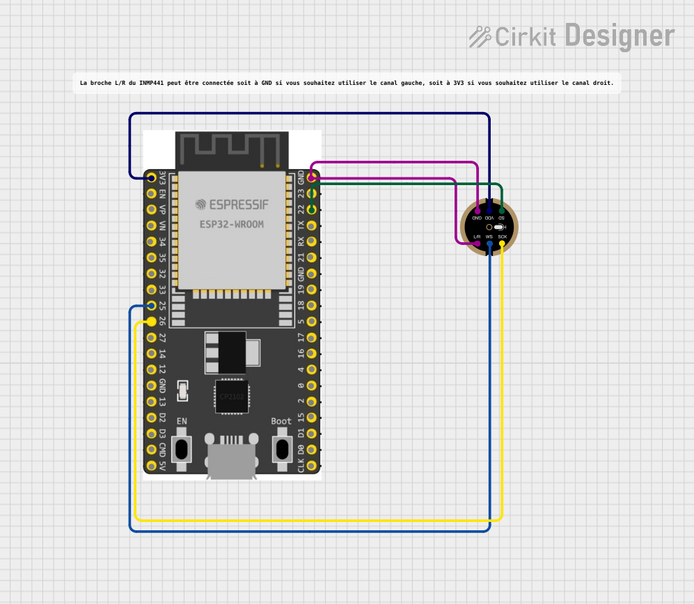
Wiring Diagram:
| INMP441 Pin | ESP32 Pin |
|---|---|
| VDD | 3.3V |
| GND | GND |
| WS | GPIO25 |
| SCK | GPIO26 |
| SD | GPIO22 |
| L/R | GND (Left) |
Example Code:
#include <driver/i2s.h>

// I2S configuration
#define I2S_NUM         I2S_NUM_0  // I2S port number
#define I2S_WS          25         // Word Select pin
#define I2S_SCK         26         // Serial Clock pin
#define I2S_SD          22         // Serial Data pin

void setup() {
  // Configure I2S
  i2s_config_t i2s_config = {
    .mode = (i2s_mode_t)(I2S_MODE_MASTER | I2S_MODE_RX), // Master mode, receive only
    .sample_rate = 16000,                               // Sampling rate
    .bits_per_sample = I2S_BITS_PER_SAMPLE_16BIT,       // 16-bit audio
    .channel_format = I2S_CHANNEL_FMT_ONLY_LEFT,        // Left channel only
    .communication_format = I2S_COMM_FORMAT_I2S,        // I2S format
    .intr_alloc_flags = ESP_INTR_FLAG_LEVEL1,           // Interrupt level
    .dma_buf_count = 8,                                 // Number of DMA buffers
    .dma_buf_len = 64                                   // Length of each DMA buffer
  };

  // Configure I2S pins
  i2s_pin_config_t pin_config = {
    .bck_io_num = I2S_SCK,  // Serial Clock pin
    .ws_io_num = I2S_WS,    // Word Select pin
    .data_out_num = -1,     // Not used (output pin)
    .data_in_num = I2S_SD   // Serial Data pin
  };

  // Install and start I2S driver
  i2s_driver_install(I2S_NUM, &i2s_config, 0, NULL);
  i2s_set_pin(I2S_NUM, &pin_config);
}

void loop() {
  // Buffer to store audio data
  uint8_t audio_data[128];
  size_t bytes_read;

  // Read audio data from INMP441
  i2s_read(I2S_NUM, audio_data, sizeof(audio_data), &bytes_read, portMAX_DELAY);

  // Process audio data (e.g., send to a server or save to SD card)
}
Notes:
- The above code configures the ESP32 to read audio data from the INMP441 at a 16 kHz sampling rate.
- Modify the
sample_rateandbits_per_sampleparameters as needed for your application.
Troubleshooting and FAQs
Common Issues:
No Audio Data Received:
- Ensure the
L/Rpin is correctly configured for the desired channel. - Verify the I2S pins are correctly connected to the microcontroller.
- Ensure the
Distorted Audio:
- Check the power supply voltage (1.8V–3.3V) and ensure it is stable.
- Use shorter wires for I2S signals to reduce noise.
Microcontroller Not Supporting I2S:
- Use a microcontroller with native I2S support (e.g., ESP32, STM32).
- Alternatively, use an external I2S interface module.
FAQs:
Can I use the INMP441 with a 5V microcontroller? No, the INMP441 operates at 1.8V–3.3V. Use a level shifter if interfacing with a 5V microcontroller.
What is the maximum sampling rate supported? The INMP441 supports sampling rates up to 48 kHz, depending on the microcontroller's I2S configuration.
Can I use multiple INMP441 microphones in a single system? Yes, you can use multiple microphones by configuring their
L/Rpins for different channels and connecting them to separate I2S interfaces.