How to Use HLK-PM01: Examples, Pinouts, and Specs
Introduction
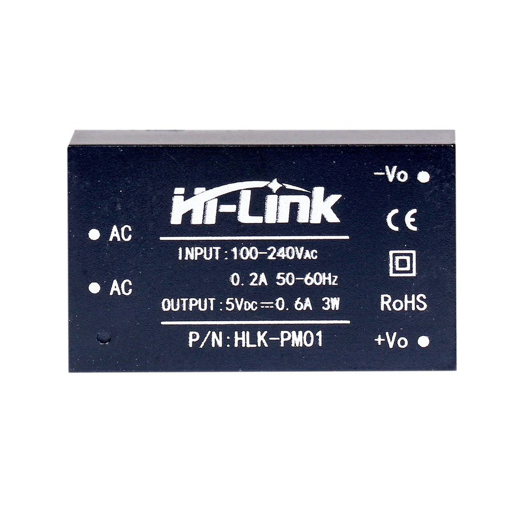
The HLK-PM01 is a compact and efficient AC-DC power module manufactured by HI-LINK. It is designed to convert a wide range of AC input voltages (85-265V AC) into a stable 5V DC output, making it ideal for powering low-power electronic devices. This module is widely used in IoT devices, home automation systems, embedded systems, and other applications requiring a reliable and compact power supply.
Explore Projects Built with HLK-PM01


Explore Projects Built with HLK-PM01
Common Applications and Use Cases
- Powering microcontrollers (e.g., Arduino, ESP8266, ESP32)
- IoT devices and smart home systems
- Low-power sensors and modules
- Embedded systems and prototyping
- Replacing bulky linear power supplies in compact designs
Technical Specifications
The HLK-PM01 is designed to provide reliable performance with the following key specifications:
| Parameter | Value |
|---|---|
| Input Voltage Range | 85-265V AC |
| Output Voltage | 5V DC |
| Output Current | 600mA (maximum) |
| Output Power | 3W |
| Efficiency | ≥ 70% |
| Ripple and Noise | ≤ 50mV |
| Operating Temperature | -20°C to +60°C |
| Storage Temperature | -40°C to +80°C |
| Dimensions | 35mm x 18mm x 15mm |
| Safety Protections | Over-voltage, Over-current, Short-circuit |
Pin Configuration and Descriptions
The HLK-PM01 module has six pins, as described in the table below:
| Pin Name | Description |
|---|---|
| AC-N | AC input (Neutral) |
| AC-L | AC input (Live) |
| +5V | DC output (Positive, 5V) |
| GND | DC output (Ground) |
| NC | Not connected (leave unconnected) |
| NC | Not connected (leave unconnected) |
Note: Ensure proper isolation between the AC and DC sides to avoid electrical hazards.
Usage Instructions
How to Use the HLK-PM01 in a Circuit
Connect the AC Input:
- Connect the
AC-Npin to the neutral wire of the AC mains. - Connect the
AC-Lpin to the live wire of the AC mains. - Use proper insulation and safety precautions when working with high-voltage AC.
- Connect the
Connect the DC Output:
- Connect the
+5Vpin to the positive terminal of your load or circuit. - Connect the
GNDpin to the ground terminal of your load or circuit.
- Connect the
Mounting and Placement:
- Place the module on a PCB or securely mount it in your project enclosure.
- Ensure adequate spacing and insulation between the AC and DC sides.
Safety Considerations:
- Use a fuse or circuit breaker on the AC input for added protection.
- Avoid touching the module while it is powered to prevent electric shock.
- Do not exceed the maximum output current (600mA) to prevent damage.
Example: Using HLK-PM01 with an Arduino UNO
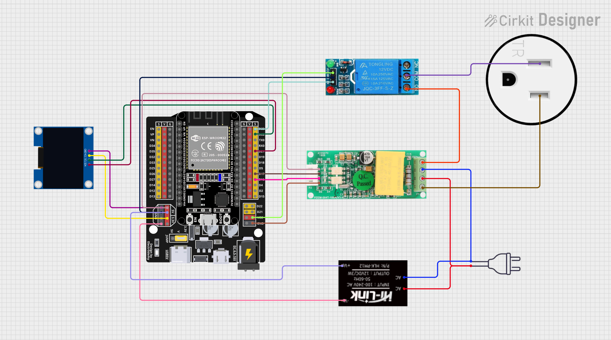
The HLK-PM01 can be used to power an Arduino UNO directly. Below is an example circuit and code:
Circuit Connections
- Connect the
+5Vpin of the HLK-PM01 to the5Vpin of the Arduino UNO. - Connect the
GNDpin of the HLK-PM01 to theGNDpin of the Arduino UNO. - Connect the
AC-NandAC-Lpins to the AC mains (use proper insulation).
Example Code
// Example code to blink an LED using Arduino UNO powered by HLK-PM01

const int ledPin = 13; // Pin connected to the onboard LED

void setup() {
  pinMode(ledPin, OUTPUT); // Set the LED pin as an output
}

void loop() {
  digitalWrite(ledPin, HIGH); // Turn the LED on
  delay(1000);                // Wait for 1 second
  digitalWrite(ledPin, LOW);  // Turn the LED off
  delay(1000);                // Wait for 1 second
}
Warning: Ensure proper isolation between the AC input and the Arduino circuit to avoid electrical hazards.
Troubleshooting and FAQs
Common Issues and Solutions
No Output Voltage:
- Check the AC input connections (
AC-NandAC-L) for proper wiring. - Verify that the AC mains voltage is within the specified range (85-265V AC).
- Ensure the load does not exceed the maximum output current (600mA).
- Check the AC input connections (
Excessive Ripple or Noise:
- Add a capacitor (e.g., 470µF) across the
+5VandGNDpins to reduce noise. - Ensure the module is not placed near high-frequency noise sources.
- Add a capacitor (e.g., 470µF) across the
Module Overheating:
- Check if the load exceeds the maximum power rating (3W).
- Ensure proper ventilation and avoid enclosing the module in a confined space.
Interference with Other Devices:
- Use an EMI filter on the AC input to reduce electromagnetic interference.
FAQs
Q1: Can the HLK-PM01 be used with 3.3V devices?
A1: No, the HLK-PM01 provides a fixed 5V output. You can use a voltage regulator (e.g., AMS1117-3.3) to step down the 5V output to 3.3V.
Q2: Is the HLK-PM01 safe for long-term use?
A2: Yes, the HLK-PM01 is designed for reliable long-term operation, provided it is used within its specified limits and with proper safety precautions.
Q3: Can I use the HLK-PM01 outdoors?
A3: The HLK-PM01 is not waterproof or weatherproof. It should only be used in indoor, dry environments.
Q4: What is the purpose of the NC pins?
A4: The NC (Not Connected) pins are unused and should be left unconnected in your circuit.
By following the guidelines and precautions outlined in this documentation, you can safely and effectively use the HLK-PM01 in your projects.