How to Use USB-C Breakout: Examples, Pinouts, and Specs
Introduction
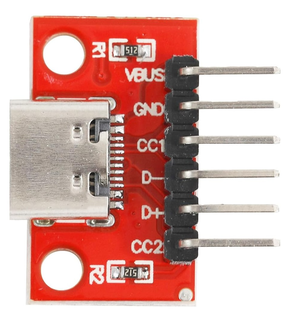
The USB-C Breakout by Cermant is a compact and versatile breakout board designed to provide easy access to the pins of a USB-C connector. This component simplifies prototyping and testing of USB-C connections, enabling developers to integrate USB-C functionality into their projects without the need for complex soldering or custom PCBs.
Explore Projects Built with USB-C Breakout


Explore Projects Built with USB-C Breakout
Common Applications and Use Cases
- Prototyping USB-C power delivery (PD) circuits
- Testing USB-C data transfer capabilities
- Developing USB-C-based devices, such as chargers, hubs, or peripherals
- Educational purposes for learning USB-C pinout and functionality
Technical Specifications
The USB-C Breakout board is designed to expose the USB-C connector's pins in a user-friendly format. Below are the key technical details:
Key Specifications
- Connector Type: USB Type-C (24-pin)
- Voltage Rating: Up to 20V (supports USB Power Delivery)
- Current Rating: Up to 5A (depending on the connected USB-C source)
- Data Protocols Supported: USB 2.0, USB 3.1, USB 3.2 (depending on implementation)
- Board Dimensions: 25mm x 20mm
- Pin Pitch: 2.54mm (standard breadboard-compatible spacing)
Pin Configuration and Descriptions
The USB-C Breakout board exposes the following pins from the USB-C connector:
| Pin Name | Description | Notes |
|---|---|---|
| GND | Ground | Common ground for power and data |
| VBUS | Power input/output (5V-20V) | Voltage depends on USB-C source |
| CC1, CC2 | Configuration Channel | Used for USB-C cable orientation detection |
| D+, D- | USB 2.0 Data Lines | For low-speed and full-speed data transfer |
| TX1+, TX1- | USB 3.x Transmit Pair 1 | High-speed data transfer (SuperSpeed) |
| RX1+, RX1- | USB 3.x Receive Pair 1 | High-speed data transfer (SuperSpeed) |
| TX2+, TX2- | USB 3.x Transmit Pair 2 | Used in alternate cable orientations |
| RX2+, RX2- | USB 3.x Receive Pair 2 | Used in alternate cable orientations |
| SBU1, SBU2 | Sideband Use | For alternate modes (e.g., audio, video) |
Note: Not all pins may be required for basic USB-C functionality. For example, USB 2.0 communication only requires
D+,D-,VBUS, andGND.
Usage Instructions
How to Use the USB-C Breakout in a Circuit
- Connect the Breakout Board:
- Solder header pins to the breakout board for easy breadboard use.
- Alternatively, use wires to directly connect the breakout board to your circuit.
- Power Supply:
- Connect the
VBUSpin to your circuit's power input. Ensure the voltage and current ratings match your device's requirements. - Connect the
GNDpin to the common ground of your circuit.
- Connect the
- Data Communication:
- For USB 2.0 communication, connect the
D+andD-pins to the corresponding data lines of your microcontroller or device. - For USB 3.x communication, connect the
TXandRXpairs as needed.
- For USB 2.0 communication, connect the
- Configuration Channel (CC):
- Use the
CC1andCC2pins to detect cable orientation and negotiate power delivery if required.
- Use the
Important Considerations and Best Practices
- Voltage and Current Limits: Ensure that the connected USB-C source does not exceed the voltage and current ratings of your circuit.
- Cable Orientation: USB-C is reversible. Use the
CC1andCC2pins to detect the orientation and configure your circuit accordingly. - Data Protocols: Verify that your circuit supports the desired USB protocol (e.g., USB 2.0 or USB 3.x).
- ESD Protection: Consider adding external ESD protection components to safeguard the breakout board and connected devices.
Example: Connecting to an Arduino UNO
Below is an example of using the USB-C Breakout to power an Arduino UNO and read data from a USB-C device.
Circuit Connections
- Connect
VBUSto the Arduino'sVINpin. - Connect
GNDto the Arduino'sGNDpin. - Connect
D+andD-to the Arduino's serial communication pins (if applicable).
Sample Code
// Example: Reading data from a USB-C device connected to the breakout board
// Note: This example assumes a USB-to-serial converter is used for data transfer.

void setup() {
  Serial.begin(9600); // Initialize serial communication at 9600 baud
  Serial.println("USB-C Breakout Test");
}

void loop() {
  if (Serial.available() > 0) {
    // Read incoming data from the USB-C device
    char data = Serial.read();
    Serial.print("Received: ");
    Serial.println(data);
  }
}
Note: The Arduino UNO does not natively support USB-C communication. Use a USB-to-serial converter or a compatible microcontroller for advanced USB-C features.
Troubleshooting and FAQs
Common Issues
- No Power Output:
- Cause: Incorrect connection to
VBUSorGND. - Solution: Verify the power source and ensure proper connections.
- Cause: Incorrect connection to
- Data Transfer Fails:
- Cause: Incorrect wiring of
D+andD-or unsupported protocol. - Solution: Check the pin connections and ensure the device supports the desired USB protocol.
- Cause: Incorrect wiring of
- Cable Orientation Not Detected:
- Cause:
CC1andCC2pins not connected or configured. - Solution: Use pull-down resistors or a USB-C controller IC to handle orientation detection.
- Cause:
FAQs
Q: Can this breakout board handle USB Power Delivery (PD)?
- A: Yes, the board supports USB PD up to 20V and 5A. However, additional circuitry is required to negotiate power delivery.
Q: Is this breakout board compatible with USB 3.x?
- A: Yes, the board exposes the necessary pins for USB 3.x communication. Ensure your circuit supports the protocol.
Q: Can I use this breakout board for video output (e.g., HDMI over USB-C)?
- A: Yes, but additional components or ICs are required to implement alternate modes like HDMI.
By following this documentation, you can effectively integrate the Cermant USB-C Breakout into your projects for prototyping and testing USB-C functionality.