How to Use Wire Splitter : Examples, Pinouts, and Specs
Introduction
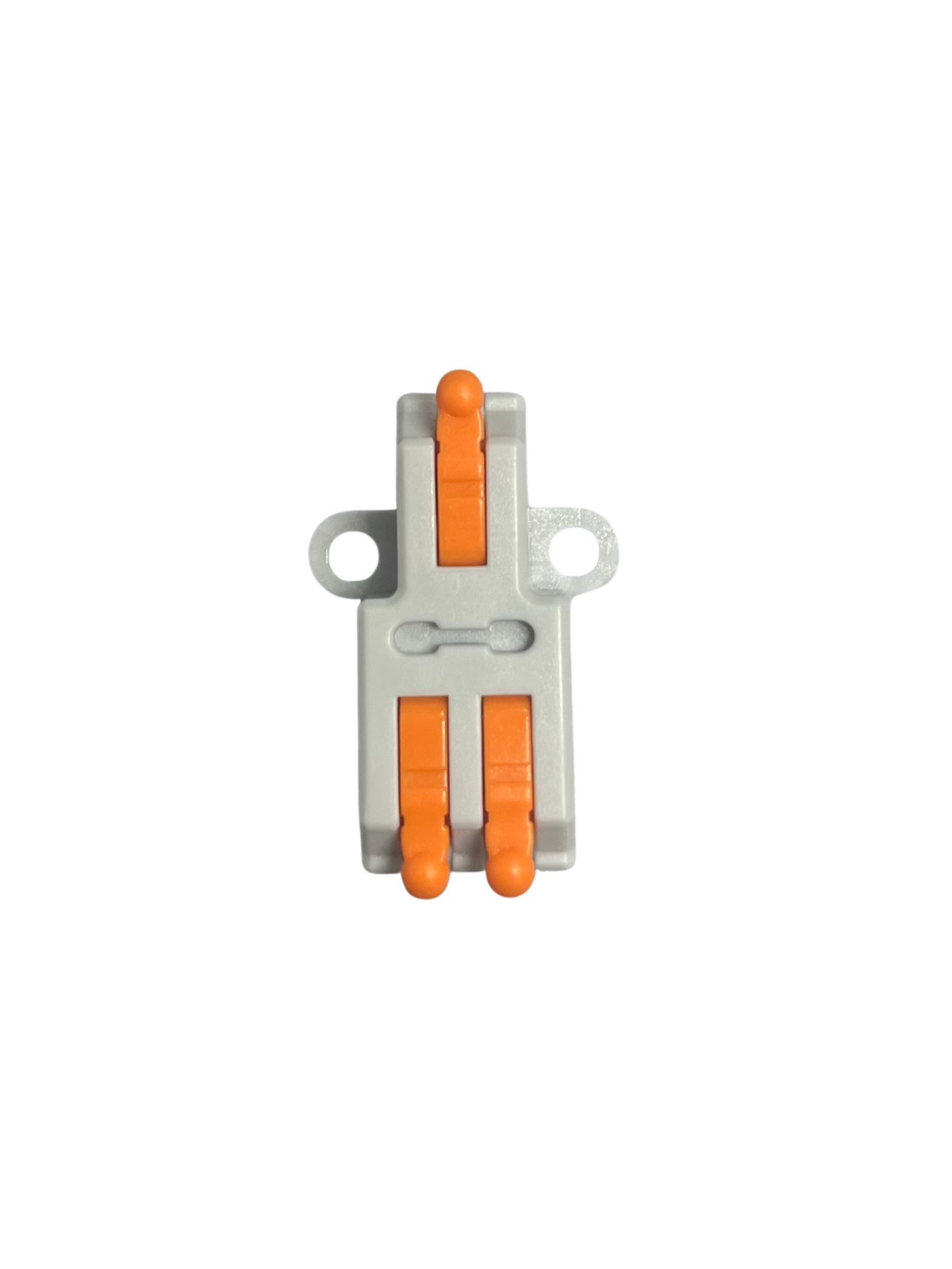
A wire splitter is a device used to divide a single electrical wire into multiple outputs, enabling the connection of several devices to a single power source. It is commonly used in electrical and electronic systems where multiple components need to share the same power supply or signal line. Wire splitters are available in various configurations, such as 1-to-2, 1-to-3, or even higher output splits, depending on the application.
Explore Projects Built with Wire Splitter


Explore Projects Built with Wire Splitter
Common Applications and Use Cases
- Power distribution in low-voltage DC circuits (e.g., LED strips, fans, sensors)
- Signal splitting for audio, video, or data transmission
- Connecting multiple devices to a single power adapter
- Automotive wiring for accessories like lights or chargers
- Prototyping and testing circuits in electronics projects
Technical Specifications
The technical specifications of a wire splitter depend on its design and intended use. Below are general specifications for a typical low-voltage DC wire splitter:
| Specification | Details |
|---|---|
| Input Voltage Range | 3V to 24V DC |
| Maximum Current Rating | 5A (varies by model; check product label for exact rating) |
| Number of Outputs | 2, 3, or more (depending on the splitter type) |
| Wire Gauge | 18 AWG to 24 AWG (varies by model) |
| Connector Type | Bare wire, barrel jack, or custom connectors (e.g., JST, Molex) |
| Insulation Material | PVC or silicone (for flexibility and durability) |
| Operating Temperature | -20°C to 70°C |
Pin Configuration and Descriptions
For a basic 1-to-2 wire splitter with bare wire ends, the pin configuration is as follows:
| Pin Name | Description |
|---|---|
| Input (+) | Positive input wire from the power source |
| Input (-) | Negative input wire (ground) from the power source |
| Output 1 (+) | Positive output wire to the first device |
| Output 1 (-) | Negative output wire (ground) to the first device |
| Output 2 (+) | Positive output wire to the second device |
| Output 2 (-) | Negative output wire (ground) to the second device |
For splitters with connectors, refer to the product's datasheet for specific pinouts.
Usage Instructions
How to Use the Component in a Circuit
- Identify the Input and Output Wires: Check the markings or color codes on the wire splitter. Typically, red wires indicate positive (+), and black wires indicate negative (-).
- Connect the Input Wires: Attach the input wires of the splitter to the power source. Ensure proper polarity to avoid damage to connected devices.
- Connect the Output Wires: Attach the output wires to the devices you want to power. Double-check the connections to ensure correct polarity.
- Secure the Connections: Use soldering, wire nuts, or connectors to secure the connections and prevent accidental disconnections.
- Test the Circuit: Power on the circuit and verify that all connected devices are functioning correctly.
Important Considerations and Best Practices
- Current Rating: Ensure the total current drawn by all connected devices does not exceed the splitter's maximum current rating.
- Voltage Compatibility: Verify that the input voltage matches the voltage requirements of the connected devices.
- Wire Gauge: Use a wire splitter with an appropriate wire gauge to handle the current without overheating.
- Short Circuit Protection: Consider adding a fuse or circuit breaker to protect the splitter and connected devices from short circuits.
- Avoid Overloading: Distribute the load evenly across the outputs to prevent overheating or damage.
Example: Connecting a Wire Splitter to an Arduino UNO
A wire splitter can be used to power both an Arduino UNO and an external device (e.g., an LED strip) from a single power source. Below is an example:
- Connect the input wires of the splitter to a 12V DC power adapter.
- Connect one output pair to the Arduino UNO's barrel jack (center positive).
- Connect the other output pair to the LED strip's power input.
// Example Arduino code to control an LED strip powered via a wire splitter
// Ensure the LED strip is connected to the splitter and the Arduino is powered
// through the same splitter.

const int ledPin = 9; // Pin connected to the LED strip's control input

void setup() {
  pinMode(ledPin, OUTPUT); // Set the LED pin as an output
}

void loop() {
  digitalWrite(ledPin, HIGH); // Turn the LED strip on
  delay(1000);               // Wait for 1 second
  digitalWrite(ledPin, LOW);  // Turn the LED strip off
  delay(1000);               // Wait for 1 second
}
Troubleshooting and FAQs
Common Issues Users Might Face
Devices Not Powering On
- Cause: Incorrect wiring or reversed polarity.
- Solution: Double-check the connections and ensure proper polarity.
Overheating Wires
- Cause: Exceeding the splitter's current rating.
- Solution: Reduce the load or use a splitter with a higher current rating.
Voltage Drop Across Outputs
- Cause: High current draw or long wire lengths.
- Solution: Use thicker wires or reduce the load on the splitter.
Short Circuit
- Cause: Exposed wires touching each other.
- Solution: Insulate all connections properly and use heat shrink tubing or electrical tape.
Solutions and Tips for Troubleshooting
- Use a multimeter to check the voltage and continuity of the wires.
- If a device is not working, test it with a direct connection to the power source to rule out issues with the splitter.
- For splitters with connectors, ensure the connectors are securely plugged in and free of debris.
By following these guidelines, you can effectively use a wire splitter in your electronic projects and ensure reliable performance.