How to Use ATGM336H: Examples, Pinouts, and Specs
Introduction
The ATGM336H is a high-performance GPS module designed to deliver precise positioning data. It features a built-in antenna, low power consumption, and supports multiple communication interfaces, making it versatile for a wide range of applications. This module is commonly used in robotics, drones, automotive systems, and other projects requiring reliable GPS functionality. Its compact design and ease of integration make it a popular choice for both hobbyists and professionals.
Explore Projects Built with ATGM336H
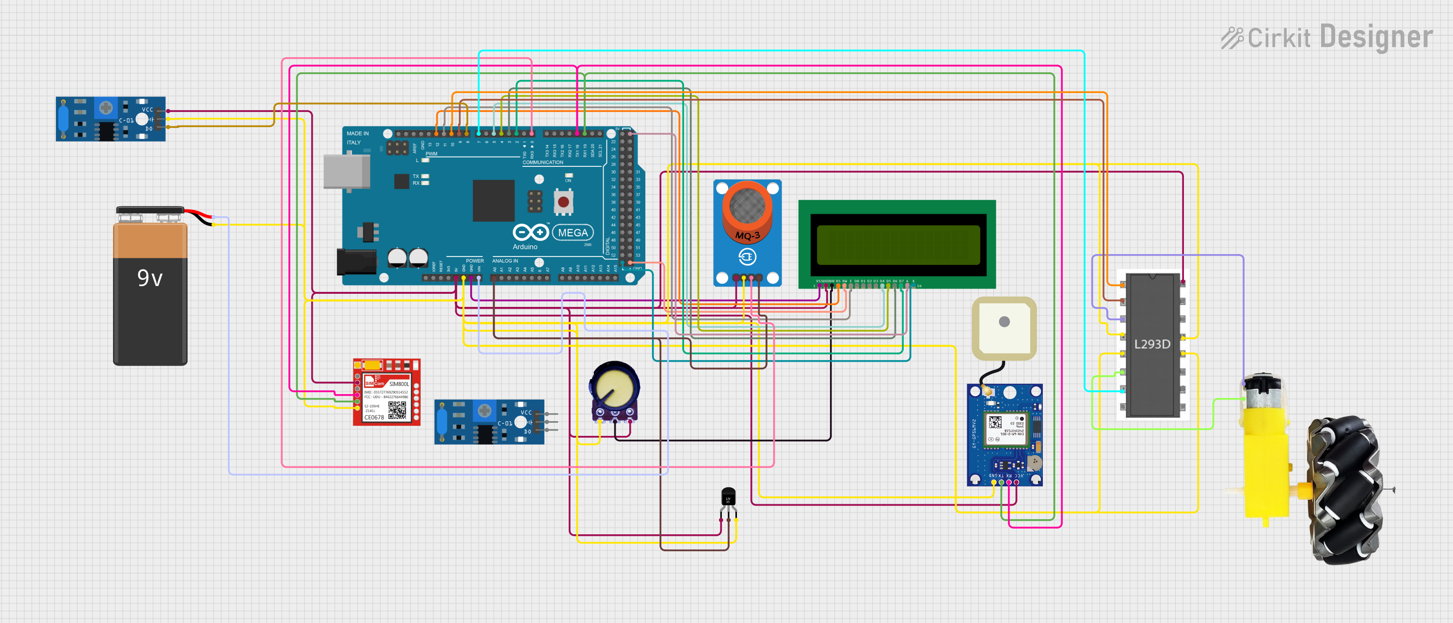
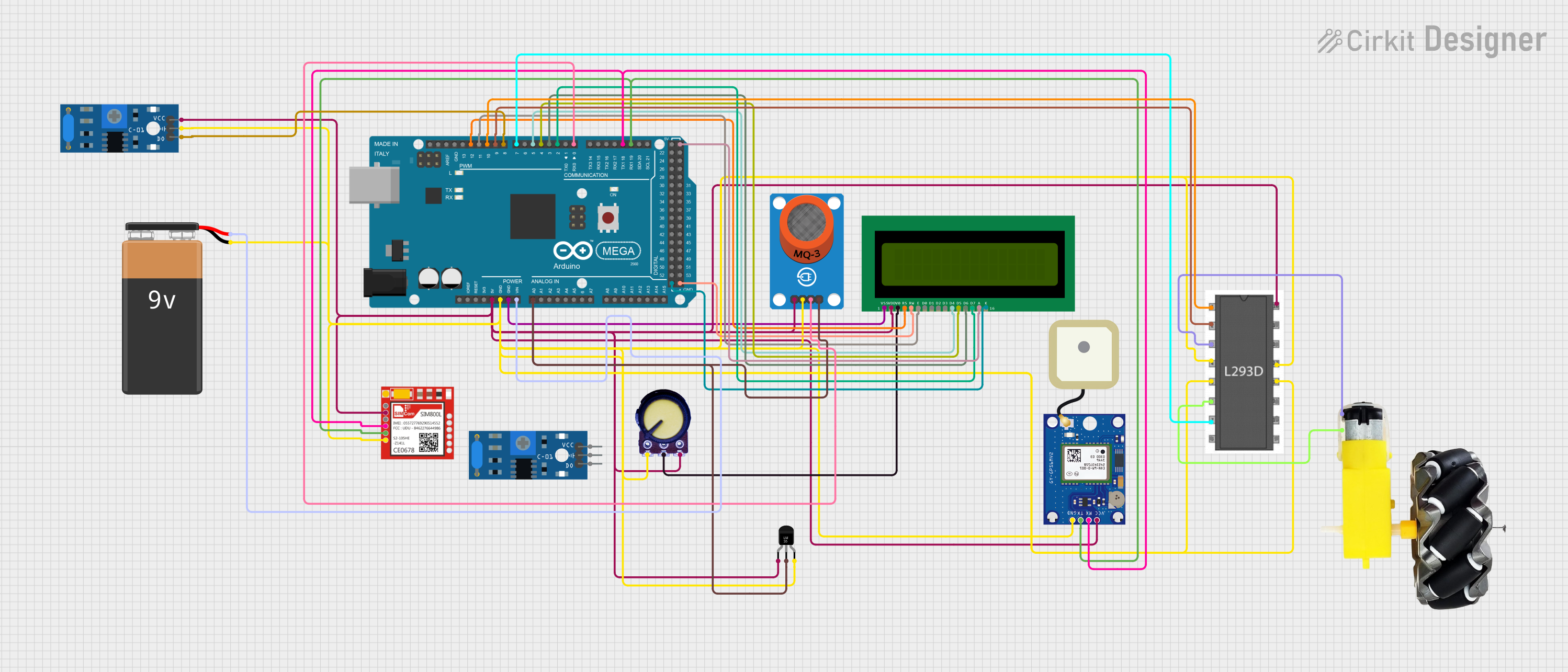
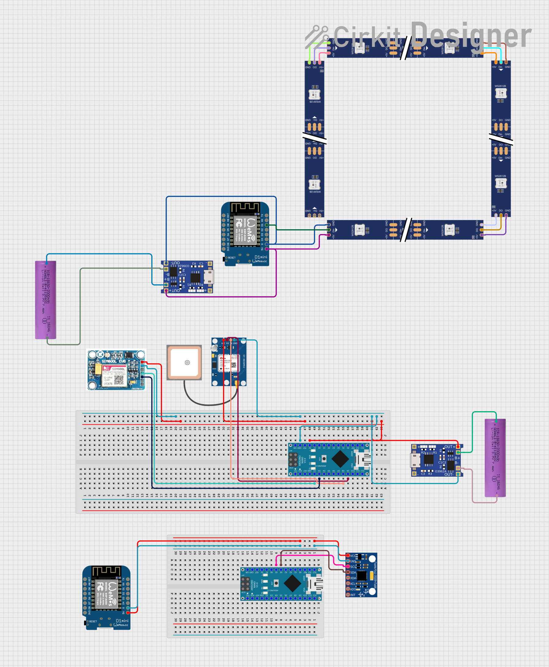
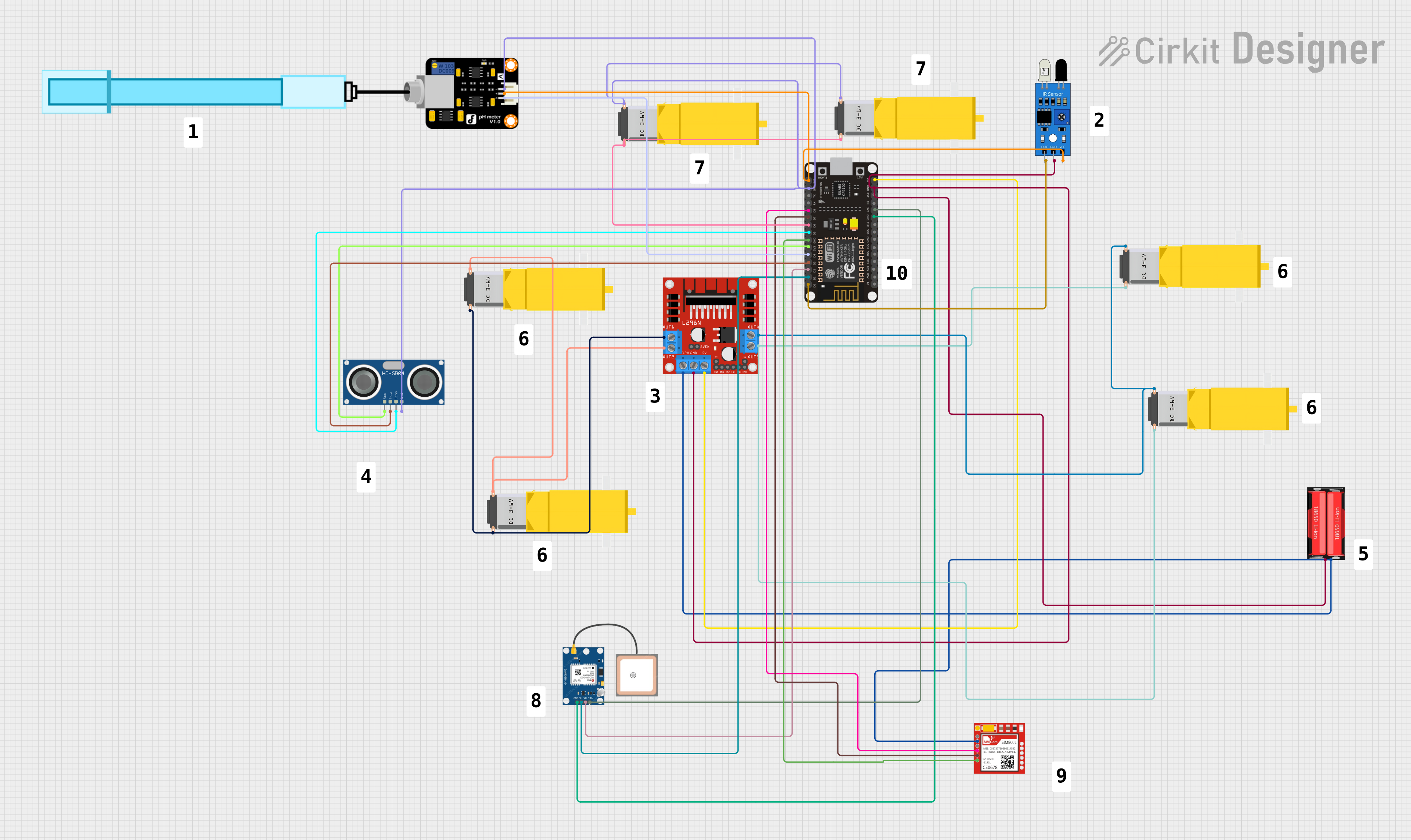
Explore Projects Built with ATGM336H
Common Applications:
- Robotics navigation systems
- Drone flight control and positioning
- Automotive GPS tracking
- IoT devices requiring geolocation
- Outdoor navigation and mapping systems
Technical Specifications
The ATGM336H GPS module is designed to provide high accuracy and reliable performance. Below are its key technical details:
Key Specifications:
| Parameter | Value |
|---|---|
| Supply Voltage | 3.0V to 5.0V |
| Operating Current | 25mA (typical) |
| Communication Interfaces | UART, I2C |
| Positioning Accuracy | 2.5 meters CEP (Circular Error Probable) |
| Cold Start Time | < 35 seconds |
| Hot Start Time | < 1 second |
| Update Rate | 1Hz to 10Hz |
| Operating Temperature | -40°C to +85°C |
| Dimensions | 16mm x 12.2mm x 2.4mm |
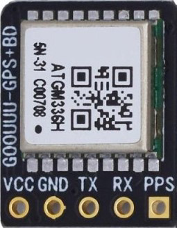
Pin Configuration:
The ATGM336H module has a straightforward pinout for easy integration into circuits. Below is the pin configuration:
| Pin Number | Pin Name | Description |
|---|---|---|
| 1 | VCC | Power supply input (3.0V to 5.0V) |
| 2 | GND | Ground connection |
| 3 | TXD | UART Transmit Data (output) |
| 4 | RXD | UART Receive Data (input) |
| 5 | PPS | Pulse Per Second output for timing applications |
| 6 | NC | Not connected |
Usage Instructions
The ATGM336H GPS module is easy to use and can be integrated into a variety of projects. Below are the steps and best practices for using the module:
Connecting the ATGM336H to a Microcontroller:
- Power Supply: Connect the
VCCpin to a 3.3V or 5V power source and theGNDpin to ground. - UART Communication: Connect the
TXDpin of the module to the RX pin of the microcontroller, and theRXDpin of the module to the TX pin of the microcontroller. - Optional PPS Pin: If precise timing is required, connect the
PPSpin to a GPIO pin on the microcontroller.
Example: Using the ATGM336H with an Arduino UNO
The following example demonstrates how to interface the ATGM336H with an Arduino UNO to read GPS data via UART.
Circuit Diagram:
- Connect
VCCto the Arduino's 5V pin. - Connect
GNDto the Arduino's GND pin. - Connect
TXDof the ATGM336H to the Arduino's RX (pin 0). - Connect
RXDof the ATGM336H to the Arduino's TX (pin 1).
Arduino Code:
#include <SoftwareSerial.h>

// Define RX and TX pins for SoftwareSerial
SoftwareSerial gpsSerial(10, 11); // RX = pin 10, TX = pin 11

void setup() {
  Serial.begin(9600); // Initialize Serial Monitor at 9600 baud
  gpsSerial.begin(9600); // Initialize GPS module at 9600 baud

  Serial.println("ATGM336H GPS Module Test");
}

void loop() {
  // Check if data is available from the GPS module
  while (gpsSerial.available()) {
    char c = gpsSerial.read(); // Read one character from GPS
    Serial.print(c); // Print the character to the Serial Monitor
  }
}
Best Practices:
- Ensure the module is placed in an open area with a clear view of the sky for optimal GPS signal reception.
- Use decoupling capacitors near the power supply pins to reduce noise.
- Avoid placing the module near high-frequency components or metal enclosures that may interfere with GPS signals.
Troubleshooting and FAQs
Common Issues and Solutions:
No GPS Data Received:
- Cause: Poor signal reception or incorrect wiring.
- Solution: Ensure the module is in an open area with a clear view of the sky. Double-check the wiring connections.
Long Time to Acquire GPS Fix:
- Cause: Cold start or weak signal.
- Solution: Allow the module sufficient time to acquire satellite data. Use an external active antenna if necessary.
Data Corruption or Unreadable Output:
- Cause: Mismatched baud rate.
- Solution: Verify that the baud rate of the GPS module matches the microcontroller's UART settings (default is 9600).
Module Not Powering On:
- Cause: Insufficient power supply.
- Solution: Ensure the power supply voltage is within the 3.0V to 5.0V range and can provide at least 25mA of current.
FAQs:
Q: Can the ATGM336H be used indoors?
A: While the module can function indoors, GPS signal reception may be weak or unavailable. For indoor use, consider using an external active antenna.Q: What is the default baud rate of the ATGM336H?
A: The default baud rate is 9600.Q: Can I use the ATGM336H with a 3.3V microcontroller?
A: Yes, the module supports a supply voltage range of 3.0V to 5.0V, making it compatible with 3.3V systems.Q: How can I increase the update rate of the module?
A: The update rate can be configured up to 10Hz using specific NMEA commands sent to the module.
By following this documentation, users can effectively integrate the ATGM336H GPS module into their projects and troubleshoot common issues with ease.