Cirkit Designer Logo
Cirkit Designer
Your all-in-one circuit design IDE
Home / 
Component Documentation

How to Use Mini-360 DC-DC Step Down Buck Converter: Examples, Pinouts, and Specs

Image of Mini-360 DC-DC Step Down Buck Converter
Cirkit Designer LogoDesign with Mini-360 DC-DC Step Down Buck Converter in Cirkit Designer

Introduction

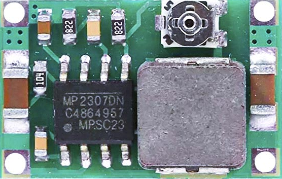
The Mini-360 DC-DC Step Down Buck Converter is a compact, high-efficiency voltage regulator designed to step down voltage from a higher level to a lower level, using the principles of buck conversion. This component is widely used in battery-powered devices, power supplies, and DIY electronics projects where a specific lower voltage is required from a higher voltage source.

Explore Projects Built with Mini-360 DC-DC Step Down Buck Converter

Use Cirkit Designer to design, explore, and prototype these projects online. Some projects support real-time simulation. Click "Open Project" to start designing instantly!
Dual Motor Control Circuit with Directional Switching and Voltage Regulation
Image of Pencuci Kipas: A project utilizing Mini-360 DC-DC Step Down Buck Converter in a practical application
This circuit features a 12V battery connected through a rocker switch to two buck converters, one of which steps down the voltage to power two DC mini metal gear motors, and the other is connected to a directional switch that controls a third DC mini metal gear motor. The XL4015 5A DC Buck Step-down converter's output is connected to two motors, allowing them to run at a reduced voltage, while the other buck converter's output is routed through a directional switch to control the direction of the third motor.
Cirkit Designer LogoOpen Project in Cirkit Designer
Battery-Powered DC Generator with XL4015 Buck Converter
Image of conveyor: A project utilizing Mini-360 DC-DC Step Down Buck Converter in a practical application
This circuit consists of a 12V battery connected to a rocker switch, which controls the input to an XL4015 DC Buck Step-down converter. The converter steps down the voltage to power a DC generator, with the generator's output connected back to the converter to form a feedback loop.
Cirkit Designer LogoOpen Project in Cirkit Designer
Battery-Powered UPS with Step-Down Buck Converter and BMS
Image of Mini ups: A project utilizing Mini-360 DC-DC Step Down Buck Converter in a practical application
This circuit is a power management system that steps down a 240V AC input to a lower DC voltage using a buck converter, which then powers a 40W UPS. The UPS is controlled by a rocker switch and is backed up by a battery management system (BMS) connected to three 3.7V batteries in series, ensuring continuous power supply.
Cirkit Designer LogoOpen Project in Cirkit Designer
USB Power Supply with Overcurrent Protection
Image of USB Charging port: A project utilizing Mini-360 DC-DC Step Down Buck Converter in a practical application
This circuit is designed to step down voltage from a 12V battery to a lower voltage suitable for USB devices. It includes a buck converter connected to the battery through a fuse and fuse holder for overcurrent protection. The output of the buck converter is connected to a USB female port, providing a regulated power supply for USB-powered devices.
Cirkit Designer LogoOpen Project in Cirkit Designer

Explore Projects Built with Mini-360 DC-DC Step Down Buck Converter

Use Cirkit Designer to design, explore, and prototype these projects online. Some projects support real-time simulation. Click "Open Project" to start designing instantly!
Image of Pencuci Kipas: A project utilizing Mini-360 DC-DC Step Down Buck Converter in a practical application
Dual Motor Control Circuit with Directional Switching and Voltage Regulation
This circuit features a 12V battery connected through a rocker switch to two buck converters, one of which steps down the voltage to power two DC mini metal gear motors, and the other is connected to a directional switch that controls a third DC mini metal gear motor. The XL4015 5A DC Buck Step-down converter's output is connected to two motors, allowing them to run at a reduced voltage, while the other buck converter's output is routed through a directional switch to control the direction of the third motor.
Cirkit Designer LogoOpen Project in Cirkit Designer
Image of conveyor: A project utilizing Mini-360 DC-DC Step Down Buck Converter in a practical application
Battery-Powered DC Generator with XL4015 Buck Converter
This circuit consists of a 12V battery connected to a rocker switch, which controls the input to an XL4015 DC Buck Step-down converter. The converter steps down the voltage to power a DC generator, with the generator's output connected back to the converter to form a feedback loop.
Cirkit Designer LogoOpen Project in Cirkit Designer
Image of Mini ups: A project utilizing Mini-360 DC-DC Step Down Buck Converter in a practical application
Battery-Powered UPS with Step-Down Buck Converter and BMS
This circuit is a power management system that steps down a 240V AC input to a lower DC voltage using a buck converter, which then powers a 40W UPS. The UPS is controlled by a rocker switch and is backed up by a battery management system (BMS) connected to three 3.7V batteries in series, ensuring continuous power supply.
Cirkit Designer LogoOpen Project in Cirkit Designer
Image of USB Charging port: A project utilizing Mini-360 DC-DC Step Down Buck Converter in a practical application
USB Power Supply with Overcurrent Protection
This circuit is designed to step down voltage from a 12V battery to a lower voltage suitable for USB devices. It includes a buck converter connected to the battery through a fuse and fuse holder for overcurrent protection. The output of the buck converter is connected to a USB female port, providing a regulated power supply for USB-powered devices.
Cirkit Designer LogoOpen Project in Cirkit Designer

Common Applications and Use Cases

  • Powering microcontrollers and sensors from a higher voltage source
  • Battery-powered applications where extending battery life is crucial
  • Providing variable voltage outputs for testing electronic circuits
  • Portable electronic devices requiring regulated power supply

Technical Specifications

Key Technical Details

  • Input Voltage Range: 4.75V to 23V
  • Output Voltage Range: 1V to 17V (adjustable via onboard potentiometer)
  • Maximum Output Current: Up to 3A (adequate heat sinking is necessary for currents above 1.5A)
  • Conversion Efficiency: Up to 96%
  • Switching Frequency: 340kHz
  • Operating Temperature: -40°C to +85°C

Pin Configuration and Descriptions

Pin Number Name Description
1 VIN Input voltage (4.75V to 23V)
2 GND Ground connection
3 VOUT Output voltage (1V to 17V)
4 GND Ground connection for the output side

Usage Instructions

How to Use the Component in a Circuit

  1. Connect the input voltage source to the VIN and GND pins, ensuring that the voltage is within the specified range.
  2. Connect the load to the VOUT and GND pins.
  3. Adjust the onboard potentiometer to set the desired output voltage. Use a multimeter to monitor the output voltage while adjusting.
  4. Ensure that the input voltage is always higher than the desired output voltage.

Important Considerations and Best Practices

  • Always verify input and output voltages with a multimeter before connecting sensitive components.
  • Do not exceed the maximum input voltage of 23V to prevent damage to the converter.
  • For currents above 1.5A, ensure adequate heat sinking to prevent overheating.
  • Avoid adjusting the potentiometer while the converter is under load to prevent voltage spikes.
  • Keep the converter away from high-temperature sources and ensure proper ventilation.

Troubleshooting and FAQs

Common Issues Users Might Face

  • Output voltage is too high or too low: Ensure the potentiometer is correctly adjusted. If the issue persists, check for any damage to the potentiometer or the converter itself.
  • Converter is overheating: Reduce the load or improve heat dissipation with a heat sink or by improving airflow.
  • No output voltage: Check all connections, ensure the input voltage is within the specified range, and that the converter is not damaged.

Solutions and Tips for Troubleshooting

  • If the output voltage cannot be adjusted, replace the potentiometer or the entire converter.
  • In case of overheating, temporarily reduce the load to allow the converter to cool down and assess the need for better heat dissipation.
  • If there is no output voltage, double-check the wiring, especially the polarity of the connections, and ensure the input voltage is present and within the specified range.

Example Code for Arduino UNO

If you're using the Mini-360 DC-DC Step Down Buck Converter to power an Arduino UNO, here's an example of how you might set up the converter and a simple code snippet to demonstrate functionality.

// This example assumes you are powering an Arduino UNO with the Mini-360 Buck Converter

void setup() {
  // Initialize the Serial communication at 9600 baud rate
  Serial.begin(9600);
}

void loop() {
  // Read the input voltage on analog pin A0
  int sensorValue = analogRead(A0);
  // Convert the analog reading (which goes from 0 - 1023) to a voltage (0 - 5V)
  float voltage = sensorValue * (5.0 / 1023.0);
  // Print out the voltage to the Serial Monitor
  Serial.println(voltage);
  // Wait for a second
  delay(1000);
}

Note: In this example, the Arduino is powered through the 5V pin, which bypasses the onboard voltage regulator. The Mini-360 Buck Converter must be adjusted to provide a stable 5V output before connecting to the Arduino.

Remember to adjust the potentiometer on the Mini-360 to output exactly 5V before connecting it to the Arduino's 5V pin. Use a multimeter to verify the voltage.