
How to Use pixhawk 6c pwm breakout board: Examples, Pinouts, and Specs
 Design with pixhawk 6c pwm breakout board in Cirkit Designer
Introduction
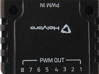
The Pixhawk 6C PWM Breakout Board is a specialized accessory designed to complement the Pixhawk 6C flight controller. It provides convenient access to Pulse Width Modulation (PWM) outputs, enabling seamless connection of servos, Electronic Speed Controllers (ESCs), and other peripherals. This breakout board simplifies wiring and enhances the modularity of UAV (Unmanned Aerial Vehicle) and robotics projects.
Explore Projects Built with pixhawk 6c pwm breakout board
 Open Project in Cirkit Designer
 Open Project in Cirkit Designer
 Open Project in Cirkit Designer
 Open Project in Cirkit Designer
Explore Projects Built with pixhawk 6c pwm breakout board
Open Project in Cirkit DesignerOpen Project in Cirkit DesignerOpen Project in Cirkit DesignerOpen Project in Cirkit DesignerCommon Applications and Use Cases
- Connecting servos for UAV control surfaces (e.g., ailerons, rudders, elevators)
- Interfacing with ESCs for motor control in drones
- Robotics projects requiring multiple PWM outputs
- Prototyping and testing of PWM-controlled devices
Technical Specifications
Key Technical Details
- Input Voltage Range: 4.5V to 5.5V (via servo rail)
- PWM Channels: Up to 8 PWM outputs
- Connector Type: Standard 3-pin servo headers (GND, VCC, Signal)
- Compatibility: Designed for Pixhawk 6C flight controller
- Dimensions: 50mm x 20mm x 10mm
- Weight: 10g
- Operating Temperature: -20°C to 60°C
Pin Configuration and Descriptions
The Pixhawk 6C PWM Breakout Board features 8 PWM output channels, each with a standard 3-pin servo header. The pinout for each channel is as follows:
| Pin Name | Description | Notes |
|---|---|---|
| GND | Ground | Connect to the ground of the system |
| VCC | Power Supply (4.5V-5.5V) | Powers connected servos or peripherals |
| Signal | PWM Signal Output | Outputs PWM signal from Pixhawk 6C |
The board also includes a power input pin for the servo rail, which must be supplied with 5V to power connected peripherals.
Usage Instructions
How to Use the Component in a Circuit
Connect the Breakout Board to Pixhawk 6C:
- Use the provided cable to connect the breakout board to the PWM output port on the Pixhawk 6C flight controller.
- Ensure the orientation of the connector matches the pin labels (GND, VCC, Signal).
Power the Servo Rail:
- Supply 5V to the servo rail using an external BEC (Battery Eliminator Circuit) or a regulated power source.
- Ensure the power source can handle the current requirements of all connected peripherals.
Connect Peripherals:
- Attach servos, ESCs, or other PWM-controlled devices to the 3-pin headers on the breakout board.
- Match the GND, VCC, and Signal pins of the peripherals to the corresponding pins on the breakout board.
Configure the Pixhawk 6C:
- Use the Pixhawk configuration software (e.g., QGroundControl) to assign functions to each PWM channel.
- Calibrate connected devices (e.g., ESCs) as needed.
Important Considerations and Best Practices
- Power Supply: Ensure the servo rail is powered with a stable 5V source. Avoid exceeding the voltage range to prevent damage.
- Current Capacity: Verify that the power source can supply sufficient current for all connected peripherals.
- Signal Integrity: Use short, high-quality cables to minimize signal degradation.
- Isolation: If using high-power devices, consider adding electrical isolation (e.g., optocouplers) to protect the flight controller.
Example Code for Arduino UNO
While the Pixhawk 6C PWM Breakout Board is primarily designed for the Pixhawk 6C, it can also be used with an Arduino UNO for prototyping. Below is an example code snippet to generate a PWM signal for a servo:
#include <Servo.h> // Include the Servo library

Servo myServo; // Create a Servo object

void setup() {
  myServo.attach(9); // Attach the servo to pin 9 on the Arduino
}

void loop() {
  myServo.write(90); // Set the servo to the 90-degree position
  delay(1000); // Wait for 1 second

  myServo.write(0); // Set the servo to the 0-degree position
  delay(1000); // Wait for 1 second
}
Note: Connect the breakout board's Signal pin to the Arduino's PWM pin (e.g., pin 9), GND to Arduino GND, and VCC to a 5V power source.
Troubleshooting and FAQs
Common Issues and Solutions
No PWM Signal Output:
- Cause: Incorrect connection between the Pixhawk 6C and the breakout board.
- Solution: Verify the cable connections and ensure proper orientation.
Servos Not Moving:
- Cause: Servo rail not powered or insufficient current supply.
- Solution: Check the power supply to the servo rail and ensure it meets the current requirements.
Erratic Servo Behavior:
- Cause: Signal interference or poor-quality cables.
- Solution: Use shielded cables and keep signal wires away from high-power lines.
Overheating Components:
- Cause: Excessive current draw from connected peripherals.
- Solution: Use a power source with higher current capacity or reduce the number of connected devices.
FAQs
Can I use this breakout board with other flight controllers?
- The board is designed for the Pixhawk 6C but may work with other controllers that have compatible PWM outputs.
What is the maximum current the servo rail can handle?
- The current capacity depends on the external power source. Ensure the source can handle the combined current draw of all connected peripherals.
Do I need to calibrate ESCs connected to the breakout board?
- Yes, ESC calibration is necessary to ensure proper operation. Follow the ESC manufacturer's instructions for calibration.
Can I use this board for non-UAV applications?
- Absolutely! The breakout board can be used in any project requiring multiple PWM outputs, such as robotics or automation systems.