How to Use JST PH 2.54 connector: Examples, Pinouts, and Specs
Introduction
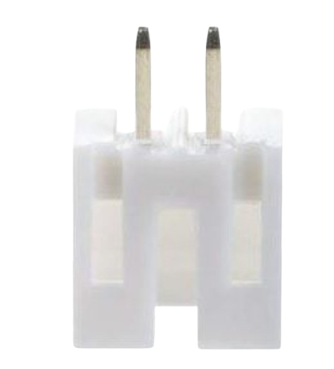
The JST PH 2.54 Connector (Manufacturer Part ID: JST 2.54 2P) is a compact, reliable connector designed for connecting wires in electronic circuits. With a 2.54mm pitch, it is widely used in low-power applications where space-saving and secure connections are essential. This connector is part of the JST PH series, known for its durability and ease of use.
Explore Projects Built with JST PH 2.54 connector

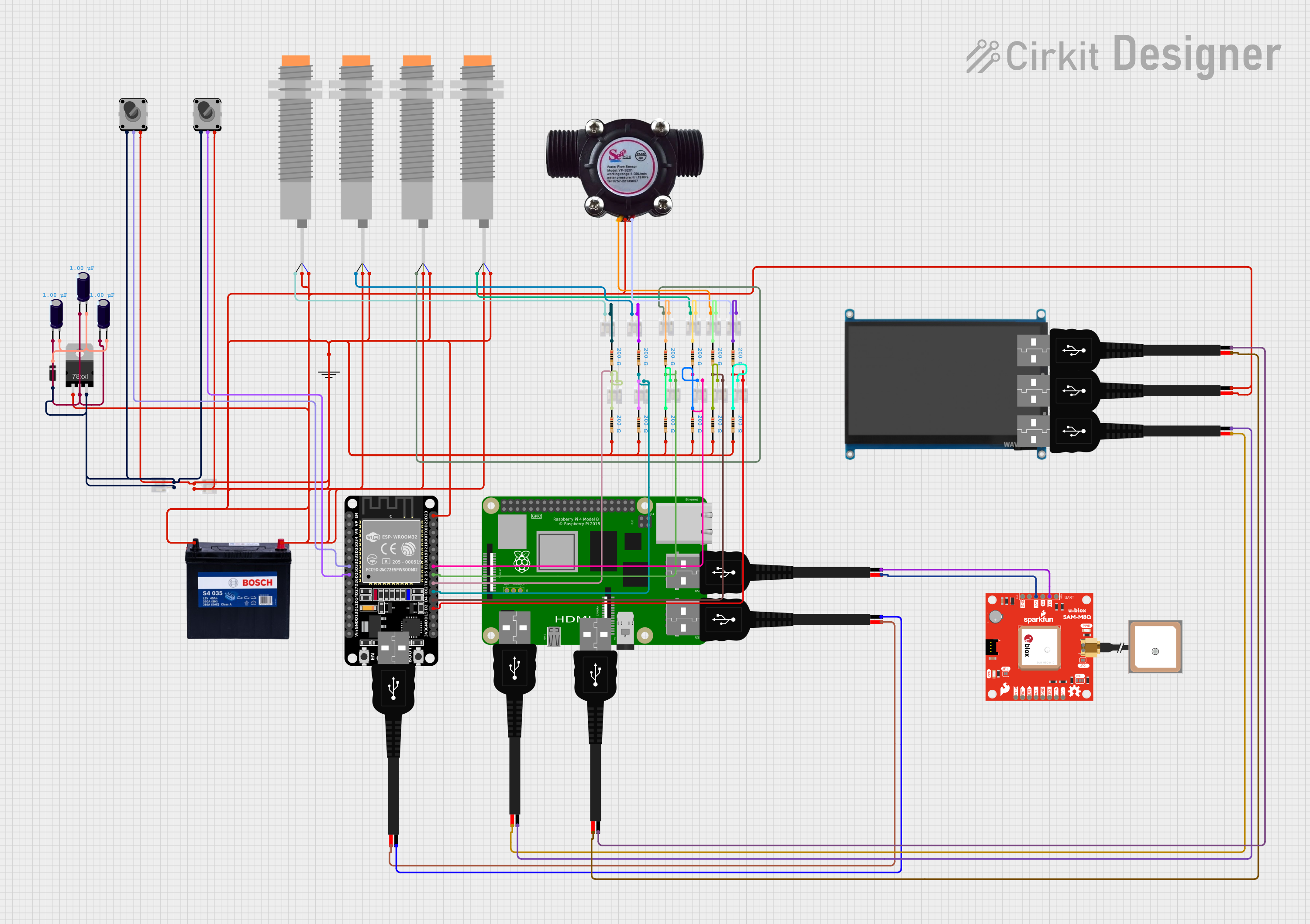

Explore Projects Built with JST PH 2.54 connector
Common Applications and Use Cases
- Consumer Electronics: Used in devices like remote controls, toys, and small appliances.
- Prototyping and Development: Ideal for connecting sensors, modules, and other components to microcontrollers.
- Battery Connections: Commonly used for connecting rechargeable batteries in small devices.
- LED Strips and Lighting: Provides a secure connection for low-power LED strips.
Technical Specifications
The following table outlines the key technical details of the JST PH 2.54 Connector:
| Parameter | Value |
|---|---|
| Manufacturer | JST |
| Series | PH |
| Pitch | 2.54mm |
| Number of Positions | 2 |
| Current Rating | 2A (maximum) |
| Voltage Rating | 100V AC/DC (maximum) |
| Wire Gauge | 28-22 AWG |
| Operating Temperature | -25°C to +85°C |
| Contact Material | Phosphor Bronze |
| Insulation Material | Nylon 66 (UL94V-0 rated) |
Pin Configuration and Descriptions
The JST PH 2.54 Connector typically has two pins (for the 2P variant). The pin configuration is as follows:
| Pin Number | Description |
|---|---|
| 1 | Positive (+) Terminal |
| 2 | Negative (-) Terminal |
Usage Instructions
How to Use the Component in a Circuit
Wire Preparation:
- Strip the insulation from the wire ends (approximately 2-3mm).
- Ensure the wire gauge is within the supported range (28-22 AWG).
Crimping:
- Use a compatible crimping tool to attach the crimp terminals to the wire ends.
- Ensure a secure crimp to avoid loose connections.
Connector Assembly:
- Insert the crimped terminals into the connector housing until they click into place.
- Verify that the terminals are securely locked in the housing.
Mating:
- Align the connector with its counterpart (e.g., a PCB header or another JST connector).
- Push the connector gently until it clicks into place.
Important Considerations and Best Practices
- Polarity: Always ensure correct polarity when connecting the wires to avoid damage to the circuit.
- Current and Voltage Limits: Do not exceed the specified current (2A) and voltage (100V) ratings.
- Secure Connections: Double-check that the terminals are fully inserted and locked into the housing.
- Crimping Tool: Use a high-quality crimping tool designed for JST PH connectors to ensure reliable connections.
- Avoid Overheating: If soldering is required, avoid overheating the connector to prevent damage to the insulation material.
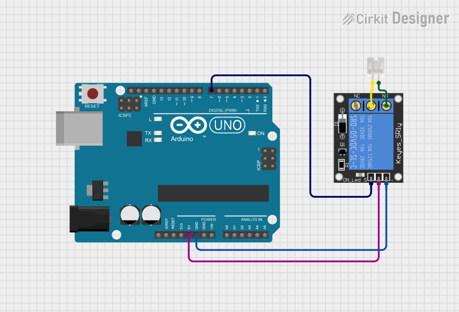
Example: Connecting to an Arduino UNO
The JST PH 2.54 Connector can be used to connect a sensor or module to an Arduino UNO. Below is an example of connecting a temperature sensor with a JST PH connector:
Circuit Diagram
- Pin 1 (Positive) → Arduino 5V
- Pin 2 (Negative) → Arduino GND
Arduino Code Example
// Example code for reading a temperature sensor connected via JST PH 2.54 connector
// Ensure the sensor's output is connected to Arduino analog pin A0

const int sensorPin = A0; // Analog pin connected to the sensor
float voltage, temperature;

void setup() {
  Serial.begin(9600); // Initialize serial communication
}

void loop() {
  int sensorValue = analogRead(sensorPin); // Read the sensor value
  voltage = sensorValue * (5.0 / 1023.0); // Convert to voltage
  temperature = (voltage - 0.5) * 100.0; // Convert voltage to temperature (Celsius)

  // Print the temperature to the Serial Monitor
  Serial.print("Temperature: ");
  Serial.print(temperature);
  Serial.println(" °C");

  delay(1000); // Wait 1 second before the next reading
}
Troubleshooting and FAQs
Common Issues Users Might Face
Loose Connections:
- Cause: Terminals not fully inserted into the housing.
- Solution: Reinsert the terminals until they click into place.
Incorrect Polarity:
- Cause: Wires connected to the wrong pins.
- Solution: Verify the pin configuration and ensure correct polarity.
Overheating or Melting:
- Cause: Exceeding current or voltage ratings, or improper soldering.
- Solution: Stay within the specified ratings and use proper soldering techniques.
Crimping Issues:
- Cause: Poor-quality crimping tool or incorrect wire gauge.
- Solution: Use a compatible crimping tool and ensure the wire gauge matches the specifications.
Solutions and Tips for Troubleshooting
- Check Continuity: Use a multimeter to check for continuity between the connector pins and the wires.
- Inspect the Connector: Look for physical damage or misaligned terminals.
- Test with a Known Good Component: Replace the connector with a new one to rule out manufacturing defects.
By following this documentation, users can effectively integrate the JST PH 2.54 Connector into their electronic projects, ensuring reliable and secure connections.