Cirkit Designer Logo
Cirkit Designer
Your all-in-one circuit design IDE
Home / 
Component Documentation

How to Use foto_interruptor: Examples, Pinouts, and Specs

Image of foto_interruptor
Cirkit Designer LogoDesign with foto_interruptor in Cirkit Designer

Introduction

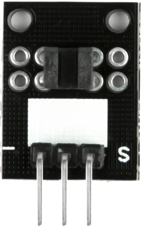
The KY-010 Photo Interrupter, manufactured by ESP32, is an optoelectronic device designed to detect the presence or absence of an object by interrupting a beam of light. It consists of an infrared LED and a phototransistor housed in a U-shaped structure. When an object passes through the gap, it blocks the light beam, causing a change in the output signal.

This component is widely used in applications such as:

  • Object detection in automation systems
  • Rotary encoders for measuring rotational speed or position
  • Line-following robots
  • Limit switches in 3D printers and CNC machines

Explore Projects Built with foto_interruptor

Use Cirkit Designer to design, explore, and prototype these projects online. Some projects support real-time simulation. Click "Open Project" to start designing instantly!
Solar-Powered Environmental Monitoring Station with Data Logging and Remote Access
Image of High cost system : A project utilizing foto_interruptor in a practical application
This circuit is a multi-sensor data logger with image capture capability, interfacing dust, temperature, current, and voltage sensors with an Arduino UNO for environmental monitoring. It includes an RTC for time-stamping, a micro SD card for data storage, and an ESP32 CAM module for image capture, programmed via an FTDI programmer.
Cirkit Designer LogoOpen Project in Cirkit Designer
Arduino UNO-Based Object Detection System with OLED Display and OV7670 Camera Module
Image of project: A project utilizing foto_interruptor in a practical application
This circuit features an Arduino UNO microcontroller interfaced with an OLED display, an OV7670 camera module, and an IR sensor. The Arduino manages image capture from the OV7670 when the IR sensor detects an object, and then displays the image on the OLED screen. The Arduino's digital and analog pins are used to control the camera and communicate with the OLED via I2C, while the IR sensor output is connected to one of the Arduino's digital pins.
Cirkit Designer LogoOpen Project in Cirkit Designer
Arduino Mega 2560 Biometric Security System with Wi-Fi Connectivity
Image of Health Monitoring Device (Collab): A project utilizing foto_interruptor in a practical application
This is a multi-functional sensor system controlled by an Arduino Mega 2560, designed to read biometric data from a pulse oximeter and an infrared thermometer, authenticate using a fingerprint scanner, display information on an OLED screen, and transmit data wirelessly via an ESP8266 module. User inputs can be received through two pushbuttons, and the system's power distribution is managed through common ground and voltage supply nets.
Cirkit Designer LogoOpen Project in Cirkit Designer
ESP32-CAM Smart Security System with PIR Sensor and BMP280, Battery-Powered and Wi-Fi Controlled
Image of ESP 32: A project utilizing foto_interruptor in a practical application
This circuit is a wireless surveillance system using an ESP32-CAM module, a PIR motion sensor, and a BMP280 sensor. The ESP32-CAM captures images and sends them via Telegram when motion is detected by the PIR sensor, while the BMP280 provides environmental data. The system is powered by a 3.7V battery, regulated to 5V using an LM340T5 7805 voltage regulator, and includes a TP4056 for battery charging.
Cirkit Designer LogoOpen Project in Cirkit Designer

Explore Projects Built with foto_interruptor

Use Cirkit Designer to design, explore, and prototype these projects online. Some projects support real-time simulation. Click "Open Project" to start designing instantly!
Image of High cost system : A project utilizing foto_interruptor in a practical application
Solar-Powered Environmental Monitoring Station with Data Logging and Remote Access
This circuit is a multi-sensor data logger with image capture capability, interfacing dust, temperature, current, and voltage sensors with an Arduino UNO for environmental monitoring. It includes an RTC for time-stamping, a micro SD card for data storage, and an ESP32 CAM module for image capture, programmed via an FTDI programmer.
Cirkit Designer LogoOpen Project in Cirkit Designer
Image of project: A project utilizing foto_interruptor in a practical application
Arduino UNO-Based Object Detection System with OLED Display and OV7670 Camera Module
This circuit features an Arduino UNO microcontroller interfaced with an OLED display, an OV7670 camera module, and an IR sensor. The Arduino manages image capture from the OV7670 when the IR sensor detects an object, and then displays the image on the OLED screen. The Arduino's digital and analog pins are used to control the camera and communicate with the OLED via I2C, while the IR sensor output is connected to one of the Arduino's digital pins.
Cirkit Designer LogoOpen Project in Cirkit Designer
Image of Health Monitoring Device (Collab): A project utilizing foto_interruptor in a practical application
Arduino Mega 2560 Biometric Security System with Wi-Fi Connectivity
This is a multi-functional sensor system controlled by an Arduino Mega 2560, designed to read biometric data from a pulse oximeter and an infrared thermometer, authenticate using a fingerprint scanner, display information on an OLED screen, and transmit data wirelessly via an ESP8266 module. User inputs can be received through two pushbuttons, and the system's power distribution is managed through common ground and voltage supply nets.
Cirkit Designer LogoOpen Project in Cirkit Designer
Image of ESP 32: A project utilizing foto_interruptor in a practical application
ESP32-CAM Smart Security System with PIR Sensor and BMP280, Battery-Powered and Wi-Fi Controlled
This circuit is a wireless surveillance system using an ESP32-CAM module, a PIR motion sensor, and a BMP280 sensor. The ESP32-CAM captures images and sends them via Telegram when motion is detected by the PIR sensor, while the BMP280 provides environmental data. The system is powered by a 3.7V battery, regulated to 5V using an LM340T5 7805 voltage regulator, and includes a TP4056 for battery charging.
Cirkit Designer LogoOpen Project in Cirkit Designer

Technical Specifications

The KY-010 Photo Interrupter is a compact and reliable device with the following specifications:

Parameter Value
Manufacturer ESP32
Part ID KY-010
Operating Voltage 3.3V to 5V
Output Type Digital (High/Low)
Gap Width 5mm
LED Wavelength Infrared (typically 940nm)
Operating Temperature -25°C to +85°C
Dimensions 10mm x 10mm x 5mm

Pin Configuration

The KY-010 has three pins, as described in the table below:

Pin Name Description
1 Signal (S) Digital output signal. Goes LOW when the light beam is interrupted.
2 VCC Power supply pin. Connect to 3.3V or 5V.
3 GND Ground pin. Connect to the ground of the circuit.

Usage Instructions

How to Use the KY-010 in a Circuit

  1. Wiring the KY-010:

    • Connect the VCC pin to a 3.3V or 5V power source.
    • Connect the GND pin to the ground of your circuit.
    • Connect the Signal pin to a digital input pin on your microcontroller (e.g., Arduino UNO).
  2. Circuit Example:

    • Place the KY-010 in a position where an object can pass through its gap to interrupt the light beam.
    • Use a pull-up resistor (e.g., 10kΩ) on the Signal pin if necessary to ensure a stable HIGH signal when the beam is not interrupted.
  3. Arduino UNO Example Code: Below is an example code snippet to read the KY-010's output using an Arduino UNO:

    // Define the pin connected to the KY-010 Signal pin
    const int photoInterrupterPin = 2;
    
    void setup() {
      pinMode(photoInterrupterPin, INPUT); // Set the pin as input
      Serial.begin(9600); // Initialize serial communication for debugging
    }
    
    void loop() {
      int sensorState = digitalRead(photoInterrupterPin); // Read the sensor state
    
      if (sensorState == LOW) {
        // The light beam is interrupted
        Serial.println("Object detected!");
      } else {
        // The light beam is not interrupted
        Serial.println("No object detected.");
      }
    
      delay(100); // Add a small delay to avoid spamming the serial monitor
    }
    

Important Considerations and Best Practices

  • Ensure the gap of the KY-010 is free from dust or debris, as this can affect its performance.
  • Avoid exposing the KY-010 to direct sunlight or strong ambient light, as this may interfere with the infrared beam.
  • Use a pull-up resistor if the output signal is unstable or noisy.
  • When using the KY-010 in high-speed applications (e.g., rotary encoders), ensure your microcontroller can handle the required sampling rate.

Troubleshooting and FAQs

Common Issues and Solutions

  1. The KY-010 does not detect objects:

    • Solution: Check the wiring and ensure the VCC and GND pins are properly connected.
    • Solution: Verify that the object passing through the gap is opaque enough to block the infrared beam.
  2. Unstable or noisy output signal:

    • Solution: Add a pull-up resistor (e.g., 10kΩ) to the Signal pin.
    • Solution: Ensure the KY-010 is not exposed to strong ambient light or infrared interference.
  3. False detections or missed objects:

    • Solution: Ensure the object is moving at a speed that allows the KY-010 to detect it reliably.
    • Solution: Check for any obstructions or misalignment in the sensor's gap.

FAQs

Q: Can the KY-010 be used with a 3.3V microcontroller like the ESP32?
A: Yes, the KY-010 is compatible with both 3.3V and 5V systems, making it suitable for use with the ESP32.

Q: What is the maximum object thickness the KY-010 can detect?
A: The KY-010 has a gap width of 5mm, so it can detect objects up to approximately 4.5mm thick.

Q: Can the KY-010 detect transparent objects?
A: Transparent objects may not block enough infrared light to trigger the sensor. For such applications, consider using a different type of sensor.

Q: How can I increase the detection range of the KY-010?
A: The detection range is fixed by the gap width and the sensitivity of the phototransistor. For larger detection ranges, consider using a reflective optical sensor instead.

By following this documentation, you can effectively integrate the KY-010 Photo Interrupter into your projects and troubleshoot any issues that arise.