Cirkit Designer Logo
Cirkit Designer
Your all-in-one circuit design IDE
Home / 
Component Documentation

How to Use 3.3v converter: Examples, Pinouts, and Specs

Image of 3.3v converter
Cirkit Designer LogoDesign with 3.3v converter in Cirkit Designer

Introduction

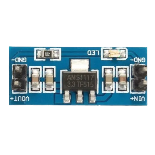
A 3.3V converter is an essential electronic component that steps down an input voltage to a stable 3.3V output. This regulated voltage is crucial for powering various low-voltage devices, such as microcontrollers, sensors, and integrated circuits, which require a precise voltage level for proper operation. Common applications include battery-powered devices, IoT gadgets, and any digital system interfacing with 3.3V logic.

Explore Projects Built with 3.3v converter

Use Cirkit Designer to design, explore, and prototype these projects online. Some projects support real-time simulation. Click "Open Project" to start designing instantly!
Battery-Powered 18650 Li-ion Charger with USB Output and Adjustable Voltage Regulator
Image of Breadboard: A project utilizing 3.3v converter in a practical application
This circuit is a battery management and power supply system that uses three 3.7V batteries connected to a 3S 10A Li-ion 18650 Charger Protection Board Module for balanced charging and protection. The system includes a TP4056 Battery Charging Protection Module for additional charging safety, a Step Up Boost Power Converter to regulate and boost the voltage, and a USB regulator to provide a stable 5V output, controlled by a push switch.
Cirkit Designer LogoOpen Project in Cirkit Designer
Battery-Powered DC-DC Converter System for Multi-Voltage Power Distribution
Image of test 1 ih: A project utilizing 3.3v converter in a practical application
This circuit converts a 38.5V battery output to multiple lower voltage levels using a series of DC-DC converters and a power module. It includes an emergency stop switch for safety and distributes power to various components such as a relay module, USB ports, and a bus servo adaptor.
Cirkit Designer LogoOpen Project in Cirkit Designer
Battery-Powered UPS with Step-Down Buck Converter and BMS
Image of Mini ups: A project utilizing 3.3v converter in a practical application
This circuit is a power management system that steps down a 240V AC input to a lower DC voltage using a buck converter, which then powers a 40W UPS. The UPS is controlled by a rocker switch and is backed up by a battery management system (BMS) connected to three 3.7V batteries in series, ensuring continuous power supply.
Cirkit Designer LogoOpen Project in Cirkit Designer
Battery-Powered Voltage Monitoring System with OLED Display using ATmega328P
Image of Voltage Meter: A project utilizing 3.3v converter in a practical application
This circuit is a voltage monitoring and display system powered by a 3.7V LiPo battery. It uses an ATmega328P microcontroller to read voltage levels from a DC voltage sensor and displays the readings on a 1.3" OLED screen. The system includes a battery charger and a step-up boost converter to ensure stable operation and power management.
Cirkit Designer LogoOpen Project in Cirkit Designer

Explore Projects Built with 3.3v converter

Use Cirkit Designer to design, explore, and prototype these projects online. Some projects support real-time simulation. Click "Open Project" to start designing instantly!
Image of Breadboard: A project utilizing 3.3v converter in a practical application
Battery-Powered 18650 Li-ion Charger with USB Output and Adjustable Voltage Regulator
This circuit is a battery management and power supply system that uses three 3.7V batteries connected to a 3S 10A Li-ion 18650 Charger Protection Board Module for balanced charging and protection. The system includes a TP4056 Battery Charging Protection Module for additional charging safety, a Step Up Boost Power Converter to regulate and boost the voltage, and a USB regulator to provide a stable 5V output, controlled by a push switch.
Cirkit Designer LogoOpen Project in Cirkit Designer
Image of test 1 ih: A project utilizing 3.3v converter in a practical application
Battery-Powered DC-DC Converter System for Multi-Voltage Power Distribution
This circuit converts a 38.5V battery output to multiple lower voltage levels using a series of DC-DC converters and a power module. It includes an emergency stop switch for safety and distributes power to various components such as a relay module, USB ports, and a bus servo adaptor.
Cirkit Designer LogoOpen Project in Cirkit Designer
Image of Mini ups: A project utilizing 3.3v converter in a practical application
Battery-Powered UPS with Step-Down Buck Converter and BMS
This circuit is a power management system that steps down a 240V AC input to a lower DC voltage using a buck converter, which then powers a 40W UPS. The UPS is controlled by a rocker switch and is backed up by a battery management system (BMS) connected to three 3.7V batteries in series, ensuring continuous power supply.
Cirkit Designer LogoOpen Project in Cirkit Designer
Image of Voltage Meter: A project utilizing 3.3v converter in a practical application
Battery-Powered Voltage Monitoring System with OLED Display using ATmega328P
This circuit is a voltage monitoring and display system powered by a 3.7V LiPo battery. It uses an ATmega328P microcontroller to read voltage levels from a DC voltage sensor and displays the readings on a 1.3" OLED screen. The system includes a battery charger and a step-up boost converter to ensure stable operation and power management.
Cirkit Designer LogoOpen Project in Cirkit Designer

Technical Specifications

Key Technical Details

  • Input Voltage Range: Typically 4.5V to 12V (varies by model)
  • Output Voltage: 3.3V DC
  • Maximum Output Current: Depends on the model (e.g., 500mA, 1A)
  • Conversion Efficiency: Up to 90% or more, depending on the load and input voltage
  • Operating Temperature: -40°C to +85°C (may vary by model)

Pin Configuration and Descriptions

Pin Number Name Description
1 VIN Input voltage (unregulated)
2 GND Ground reference for the circuit
3 VOUT Regulated 3.3V output voltage
4 EN Enable pin (logic high to enable, low to disable)
5 GND Ground reference for the circuit (may be connected to Pin 2)

Note: The pin configuration may vary depending on the specific model of the 3.3V converter. Always refer to the manufacturer's datasheet for exact details.

Usage Instructions

How to Use the Component in a Circuit

  1. Connecting Input Voltage (VIN): Connect a voltage source within the specified input range to the VIN pin. Ensure that the polarity is correct to prevent damage.
  2. Grounding (GND): Connect the GND pin(s) to the common ground of your circuit.
  3. Output Voltage (VOUT): The regulated 3.3V can be drawn from the VOUT pin. Connect this to the power input of your 3.3V devices.
  4. Enable Pin (EN): If available, the EN pin can be used to turn the converter on or off. Connect to a logic high level to enable the converter or to a logic low level to disable it.

Important Considerations and Best Practices

  • Heat Dissipation: Ensure adequate cooling if the converter is expected to handle high loads or if the input voltage is significantly higher than 3.3V.
  • Input Capacitor: Place a capacitor (e.g., 10µF) close to the VIN pin to stabilize the input supply.
  • Output Capacitor: Place a capacitor (e.g., 10µF) close to the VOUT pin to smooth out the output voltage.
  • Enable Pin Usage: If the EN pin is not used, it should be tied to a high logic level to ensure the converter is enabled.

Troubleshooting and FAQs

Common Issues

  • Converter Not Outputting 3.3V: Check input voltage and connections. Ensure the input voltage is within the specified range and that the EN pin is set high if present.
  • Overheating: Reduce the load or improve heat dissipation. Check for short circuits or incorrect connections.
  • Output Voltage Fluctuations: Ensure capacitors are installed at the input and output as recommended. Check for excessive load or noise on the input supply.

Solutions and Tips for Troubleshooting

  • Verify Connections: Double-check all connections against the circuit diagram.
  • Measure Input Voltage: Use a multimeter to confirm the input voltage is within the specified range.
  • Inspect for Damage: Look for any signs of physical damage or overheating on the converter.

FAQs

Q: Can I use the 3.3V converter with a 5V Arduino? A: Yes, you can use it to power 3.3V components from a 5V Arduino board.

Q: What happens if I exceed the maximum output current? A: Exceeding the maximum current can lead to overheating, voltage drop, or permanent damage to the converter.

Q: Is it possible to adjust the output voltage? A: Standard 3.3V converters have a fixed output. However, some models may offer an adjustable output via an external resistor or potentiometer.

Example Arduino Connection

// Example code to demonstrate how to power a 3.3V sensor with the converter

void setup() {
  // Initialize the sensor here
}

void loop() {
  // Read and process sensor data
}

Note: This example assumes that the sensor operates at 3.3V and is compatible with the logic level of the Arduino.

Remember to consult the datasheet of your specific 3.3V converter model for precise information and to verify compatibility with your application.