
How to Use ESP32-S3-N16R8: Examples, Pinouts, and Specs
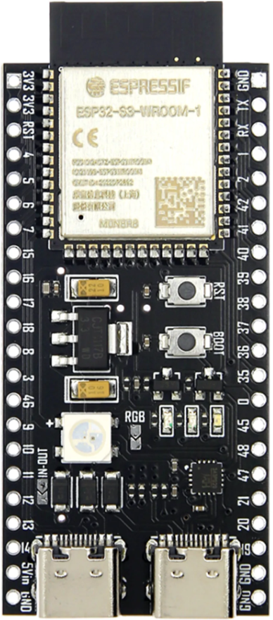
 Design with ESP32-S3-N16R8 in Cirkit Designer
Introduction
The ESP32-S3-N16R8, manufactured by Espressif, is a high-performance microcontroller designed for IoT (Internet of Things) applications and advanced processing tasks. It features a dual-core processor, integrated Wi-Fi and Bluetooth connectivity, 16MB of flash memory, and 8MB of RAM. This component is ideal for applications requiring high computational power, low power consumption, and seamless wireless communication.
Explore Projects Built with ESP32-S3-N16R8
 Open Project in Cirkit Designer
 Open Project in Cirkit Designer
 Open Project in Cirkit Designer
 Open Project in Cirkit Designer
Explore Projects Built with ESP32-S3-N16R8
Open Project in Cirkit DesignerOpen Project in Cirkit DesignerOpen Project in Cirkit DesignerOpen Project in Cirkit DesignerCommon Applications and Use Cases
- Smart home devices (e.g., smart lights, thermostats, and security systems)
- Wearable technology
- Industrial IoT systems
- Edge computing and AI/ML applications
- Wireless sensor networks
- Robotics and automation systems
Technical Specifications
Key Technical Details
| Parameter | Specification |
|---|---|
| Manufacturer | Espressif |
| Processor | Dual-core Xtensa® LX7 |
| Clock Speed | Up to 240 MHz |
| Flash Memory | 16MB |
| RAM | 8MB |
| Wireless Connectivity | Wi-Fi 802.11 b/g/n (2.4 GHz), Bluetooth 5.0 LE |
| GPIO Pins | 45 (configurable for various functions) |
| Operating Voltage | 3.0V to 3.6V |
| Power Consumption | Ultra-low power modes available |
| Interfaces | SPI, I2C, I2S, UART, ADC, DAC, PWM, USB OTG |
| Operating Temperature | -40°C to +85°C |
| Package | QFN48 (7x7 mm) |
Pin Configuration and Descriptions
The ESP32-S3-N16R8 has 45 GPIO pins, which are highly configurable for various functions. Below is a table highlighting some key pins and their default functions:
| Pin Number | Default Function | Description |
|---|---|---|
| GPIO0 | Boot Mode Selection | Used to select boot mode during startup |
| GPIO1 | UART TX | Transmit pin for UART communication |
| GPIO3 | UART RX | Receive pin for UART communication |
| GPIO18 | SPI CLK | Clock pin for SPI interface |
| GPIO19 | SPI MISO | Master In Slave Out for SPI |
| GPIO23 | SPI MOSI | Master Out Slave In for SPI |
| GPIO25 | DAC1 | Digital-to-Analog Converter Channel 1 |
| GPIO26 | DAC2 | Digital-to-Analog Converter Channel 2 |
| GPIO32 | ADC1_CH4 | Analog-to-Digital Converter Channel 4 |
| GPIO33 | ADC1_CH5 | Analog-to-Digital Converter Channel 5 |
| GPIO36 | ADC1_CH0 | Analog-to-Digital Converter Channel 0 |
| GPIO39 | ADC1_CH3 | Analog-to-Digital Converter Channel 3 |
Note: Many GPIO pins are multiplexed and can be configured for alternate functions such as PWM, I2C, or UART.
Usage Instructions
How to Use the ESP32-S3-N16R8 in a Circuit
- Power Supply: Ensure the ESP32-S3-N16R8 is powered with a stable voltage between 3.0V and 3.6V. A 3.3V regulator is commonly used.
- Boot Mode: Connect GPIO0 to GND during startup to enter bootloader mode for programming. For normal operation, leave GPIO0 unconnected or pulled high.
- Programming: Use a USB-to-UART converter to connect the ESP32-S3-N16R8 to your computer. The UART TX and RX pins (GPIO1 and GPIO3) are used for communication.
- Peripherals: Connect sensors, actuators, or other peripherals to the GPIO pins. Configure the pins in your firmware for the desired functionality (e.g., input, output, or alternate functions like I2C or SPI).
- Antenna: Ensure the onboard antenna has sufficient clearance from metallic objects to maintain optimal wireless performance.
Important Considerations and Best Practices
- Power Management: Use the ultra-low power modes (e.g., deep sleep) to extend battery life in portable applications.
- Decoupling Capacitors: Place decoupling capacitors (e.g., 0.1 µF) close to the power pins to reduce noise and ensure stable operation.
- Firmware Development: Use the Espressif ESP-IDF (IoT Development Framework) or Arduino IDE for programming. The ESP-IDF provides advanced features and better control over hardware.
- ESD Protection: Add ESD protection diodes to GPIO pins exposed to external connections to prevent damage.
Example Code for Arduino IDE
Below is an example of how to use the ESP32-S3-N16R8 to blink an LED connected to GPIO2:
// Define the GPIO pin for the LED
#define LED_PIN 2

void setup() {
  // Initialize the LED pin as an output
  pinMode(LED_PIN, OUTPUT);
}

void loop() {
  // Turn the LED on
  digitalWrite(LED_PIN, HIGH);
  delay(1000); // Wait for 1 second

  // Turn the LED off
  digitalWrite(LED_PIN, LOW);
  delay(1000); // Wait for 1 second
}
Note: Ensure the Arduino IDE is configured with the correct ESP32-S3 board settings and drivers.
Troubleshooting and FAQs
Common Issues and Solutions
Device Not Detected by Computer
- Ensure the USB-to-UART driver is installed on your computer.
- Check the connections between the ESP32-S3-N16R8 and the USB-to-UART converter.
- Verify that the ESP32-S3-N16R8 is powered correctly.
Wi-Fi or Bluetooth Not Working
- Ensure the onboard antenna has sufficient clearance from metallic objects.
- Verify that the firmware is correctly configured for Wi-Fi or Bluetooth operation.
Program Upload Fails
- Check that GPIO0 is connected to GND during programming.
- Ensure the correct COM port and board settings are selected in the IDE.
Random Resets or Instability
- Verify that the power supply is stable and within the specified voltage range.
- Add decoupling capacitors near the power pins to reduce noise.
FAQs
Q: Can the ESP32-S3-N16R8 run AI/ML models?
A: Yes, the ESP32-S3-N16R8 supports AI/ML applications using frameworks like TensorFlow Lite Micro. Its dual-core processor and 8MB of RAM make it suitable for edge computing tasks.
Q: How do I update the firmware?
A: Firmware can be updated via the UART interface using tools like esptool.py or over-the-air (OTA) updates if configured in the firmware.
Q: What is the maximum Wi-Fi range?
A: The Wi-Fi range depends on environmental factors but typically extends up to 100 meters in open spaces.
Q: Can I use the ESP32-S3-N16R8 with a 5V logic level?
A: No, the ESP32-S3-N16R8 operates at 3.3V logic levels. Use level shifters if interfacing with 5V devices.