Cirkit Designer Logo
Cirkit Designer
Your all-in-one circuit design IDE
Home / 
Component Documentation

How to Use 3 amps fuse holder: Examples, Pinouts, and Specs

Image of 3 amps fuse holder
Cirkit Designer LogoDesign with 3 amps fuse holder in Cirkit Designer

Introduction

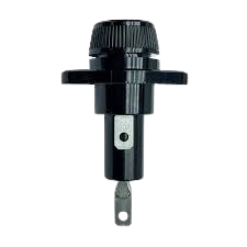
The 3 Amps Fuse Holder, manufactured by Fuse Holder (Part ID: Fuse), is a device designed to securely house a 3-amp fuse. It provides essential protection for electrical circuits by interrupting the flow of current when it exceeds the rated limit, thereby preventing damage to connected components and reducing the risk of fire or electrical hazards.

Explore Projects Built with 3 amps fuse holder

Use Cirkit Designer to design, explore, and prototype these projects online. Some projects support real-time simulation. Click "Open Project" to start designing instantly!
Basic Surge Protection Circuit with Benedict Switch
Image of DC & Monitoring Box: A project utilizing 3 amps fuse holder in a practical application
The circuit includes a Benedict Switch connected in series with a Fuse Holder and an SPD (Surge Protection Device). The SPD is also connected to a Ground reference. This configuration suggests that the circuit is designed to control power flow, protect against overcurrent with the fuse, and guard against voltage surges with the SPD, with a safe path to ground for surge dissipation.
Cirkit Designer LogoOpen Project in Cirkit Designer
USB Power Supply with Overcurrent Protection
Image of USB Charging port: A project utilizing 3 amps fuse holder in a practical application
This circuit is designed to step down voltage from a 12V battery to a lower voltage suitable for USB devices. It includes a buck converter connected to the battery through a fuse and fuse holder for overcurrent protection. The output of the buck converter is connected to a USB female port, providing a regulated power supply for USB-powered devices.
Cirkit Designer LogoOpen Project in Cirkit Designer
Battery-Powered 18650 Li-ion Charger with USB Output and Adjustable Voltage Regulator
Image of Breadboard: A project utilizing 3 amps fuse holder in a practical application
This circuit is a battery management and power supply system that uses three 3.7V batteries connected to a 3S 10A Li-ion 18650 Charger Protection Board Module for balanced charging and protection. The system includes a TP4056 Battery Charging Protection Module for additional charging safety, a Step Up Boost Power Converter to regulate and boost the voltage, and a USB regulator to provide a stable 5V output, controlled by a push switch.
Cirkit Designer LogoOpen Project in Cirkit Designer
Dual 5V Power Supply Distribution Circuit with Toggle Switch Control
Image of rfdriver: A project utilizing 3 amps fuse holder in a practical application
This circuit consists of two 5V 5A power supplies connected to an AC wall plug point, providing DC output through a 12-way connector. The ground connections from both power supplies are interconnected and also connected to the ground pins of two toggle switches. The DC outputs from the power supplies are separately connected to different pins on the 12-way connector, with each power supply output being switchable via one of the toggle switches.
Cirkit Designer LogoOpen Project in Cirkit Designer

Explore Projects Built with 3 amps fuse holder

Use Cirkit Designer to design, explore, and prototype these projects online. Some projects support real-time simulation. Click "Open Project" to start designing instantly!
Image of DC & Monitoring Box: A project utilizing 3 amps fuse holder in a practical application
Basic Surge Protection Circuit with Benedict Switch
The circuit includes a Benedict Switch connected in series with a Fuse Holder and an SPD (Surge Protection Device). The SPD is also connected to a Ground reference. This configuration suggests that the circuit is designed to control power flow, protect against overcurrent with the fuse, and guard against voltage surges with the SPD, with a safe path to ground for surge dissipation.
Cirkit Designer LogoOpen Project in Cirkit Designer
Image of USB Charging port: A project utilizing 3 amps fuse holder in a practical application
USB Power Supply with Overcurrent Protection
This circuit is designed to step down voltage from a 12V battery to a lower voltage suitable for USB devices. It includes a buck converter connected to the battery through a fuse and fuse holder for overcurrent protection. The output of the buck converter is connected to a USB female port, providing a regulated power supply for USB-powered devices.
Cirkit Designer LogoOpen Project in Cirkit Designer
Image of Breadboard: A project utilizing 3 amps fuse holder in a practical application
Battery-Powered 18650 Li-ion Charger with USB Output and Adjustable Voltage Regulator
This circuit is a battery management and power supply system that uses three 3.7V batteries connected to a 3S 10A Li-ion 18650 Charger Protection Board Module for balanced charging and protection. The system includes a TP4056 Battery Charging Protection Module for additional charging safety, a Step Up Boost Power Converter to regulate and boost the voltage, and a USB regulator to provide a stable 5V output, controlled by a push switch.
Cirkit Designer LogoOpen Project in Cirkit Designer
Image of rfdriver: A project utilizing 3 amps fuse holder in a practical application
Dual 5V Power Supply Distribution Circuit with Toggle Switch Control
This circuit consists of two 5V 5A power supplies connected to an AC wall plug point, providing DC output through a 12-way connector. The ground connections from both power supplies are interconnected and also connected to the ground pins of two toggle switches. The DC outputs from the power supplies are separately connected to different pins on the 12-way connector, with each power supply output being switchable via one of the toggle switches.
Cirkit Designer LogoOpen Project in Cirkit Designer

Common Applications and Use Cases

  • Overcurrent protection in low-power electronic circuits
  • Automotive electrical systems
  • Consumer electronics and appliances
  • Industrial control panels
  • DIY electronics projects

Technical Specifications

The following table outlines the key technical details of the 3 Amps Fuse Holder:

Parameter Value
Manufacturer Fuse Holder
Part ID Fuse
Rated Current 3 Amps
Rated Voltage Up to 250V AC
Fuse Type Compatibility Glass or ceramic cylindrical fuses
Mounting Style Panel mount or inline
Material Flame-retardant plastic and metal
Operating Temperature -20°C to 85°C
Dimensions Varies by model (e.g., 30mm x 10mm)

Pin Configuration and Descriptions

The 3 Amps Fuse Holder typically has two terminals for electrical connections. The table below describes the terminals:

Terminal Description
Terminal 1 Input terminal for connecting the power source
Terminal 2 Output terminal for connecting to the load

Usage Instructions

How to Use the Component in a Circuit

  1. Select a Compatible Fuse: Ensure the fuse used is rated for 3 amps and is compatible with the holder (e.g., glass or ceramic cylindrical fuse).
  2. Insert the Fuse: Open the fuse holder and securely place the fuse inside. Ensure proper alignment to maintain electrical contact.
  3. Connect the Terminals:
    • Connect Terminal 1 to the power source.
    • Connect Terminal 2 to the load (e.g., a circuit or device requiring protection).
  4. Secure the Fuse Holder: If the fuse holder is panel-mounted, fix it in place using screws or clips. For inline holders, ensure the connections are insulated and secure.
  5. Test the Circuit: Power on the circuit and verify that the fuse holder is functioning correctly.

Important Considerations and Best Practices

  • Fuse Rating: Always use a fuse with the correct current rating (3 amps). Using a higher-rated fuse may compromise circuit protection.
  • Connection Polarity: While fuse holders are not polarity-sensitive, ensure proper wiring to avoid loose connections.
  • Environmental Conditions: Avoid exposing the fuse holder to excessive heat, moisture, or corrosive environments.
  • Replacement: If the fuse blows, disconnect power before replacing it. Inspect the holder for damage before inserting a new fuse.

Example: Connecting to an Arduino UNO

The 3 Amps Fuse Holder can be used to protect an Arduino UNO from overcurrent. Below is an example circuit and code:

Circuit Setup

  1. Connect Terminal 1 of the fuse holder to the positive terminal of a 9V battery.
  2. Connect Terminal 2 to the VIN pin of the Arduino UNO.
  3. Connect the negative terminal of the battery to the GND pin of the Arduino UNO.

Example Code

// Example code for Arduino UNO with a 3 Amps Fuse Holder
// This code blinks an LED connected to pin 13

void setup() {
  pinMode(13, OUTPUT); // Set pin 13 as an output
}

void loop() {
  digitalWrite(13, HIGH); // Turn the LED on
  delay(1000);            // Wait for 1 second
  digitalWrite(13, LOW);  // Turn the LED off
  delay(1000);            // Wait for 1 second
}

Troubleshooting and FAQs

Common Issues Users Might Face

  1. Fuse Blows Frequently:

    • Cause: The circuit may be drawing more than 3 amps.
    • Solution: Check the circuit for short circuits or excessive load. Use a lower-power load if necessary.
  2. Loose Connections:

    • Cause: Terminals are not securely connected.
    • Solution: Ensure all connections are tight and properly insulated.
  3. Fuse Holder Overheats:

    • Cause: Poor contact between the fuse and holder terminals.
    • Solution: Inspect the holder for corrosion or damage. Replace if necessary.
  4. Fuse Does Not Blow When Overcurrent Occurs:

    • Cause: Incorrect fuse rating or faulty fuse.
    • Solution: Verify the fuse rating and replace the fuse with a properly rated one.

Solutions and Tips for Troubleshooting

  • Always disconnect power before inspecting or replacing the fuse.
  • Use a multimeter to check for continuity across the fuse holder terminals.
  • If the fuse holder is damaged, replace it immediately to ensure reliable circuit protection.

By following this documentation, users can effectively integrate and maintain the 3 Amps Fuse Holder in their electronic circuits.