Cirkit Designer Logo
Cirkit Designer
Your all-in-one circuit design IDE
Home / 
Component Documentation

How to Use Arcade Button (pink): Examples, Pinouts, and Specs

Image of Arcade Button (pink)
Cirkit Designer LogoDesign with Arcade Button (pink) in Cirkit Designer

Introduction

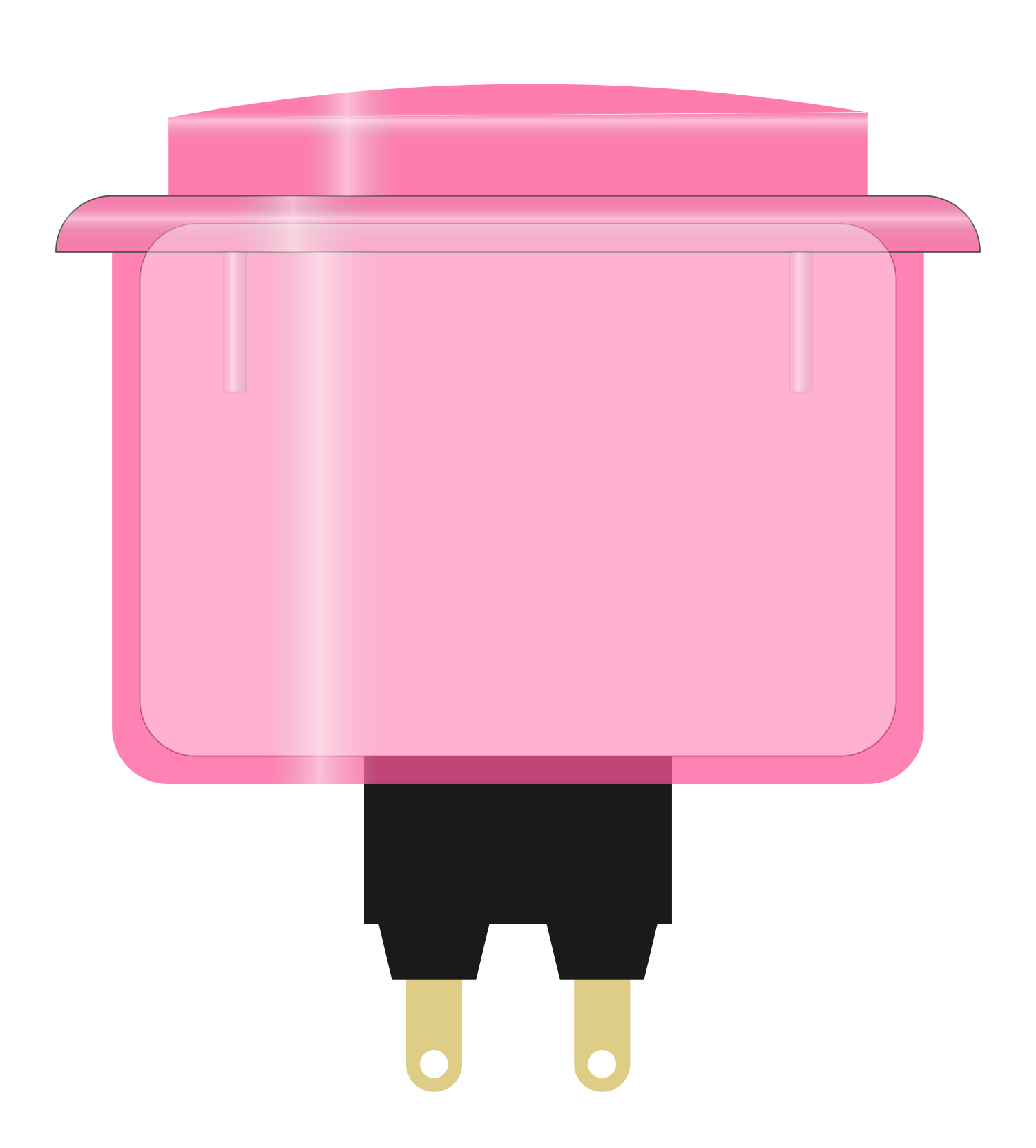
The Arcade Button in pink is a robust and tactile switch designed for high-use environments such as arcade game cabinets, interactive displays, and custom controllers. Its vibrant pink hue adds a playful and personalized touch to any project. The button is engineered for quick and responsive actuation, making it ideal for applications where user input speed and reliability are crucial.

Explore Projects Built with Arcade Button (pink)

Use Cirkit Designer to design, explore, and prototype these projects online. Some projects support real-time simulation. Click "Open Project" to start designing instantly!
Arduino UNO Controlled RGB LED Strip with Interactive Button
Image of Simon Circuit: A project utilizing Arcade Button (pink) in a practical application
This circuit features an Arduino UNO connected to a WS2812 RGB LED strip, controlled via digital pin D8. An arcade button is interfaced with the Arduino through a resistor and digital pin D3, likely for user input to control the LED strip. Power is supplied through a 2.1mm DC barrel jack, with an electrolytic capacitor for voltage smoothing, and the ground connections are shared among the components.
Cirkit Designer LogoOpen Project in Cirkit Designer
Arduino Mega 2560-Based Interactive Game with RGB LEDs, LCD Display, and DFPlayer Audio
Image of Game: A project utilizing Arcade Button (pink) in a practical application
This circuit is a game controller that uses an Arduino Mega 2560 to manage inputs from multiple arcade buttons, control RGB LEDs, display messages on an LCD, and play audio through a DFPlayer module. The system announces the winner based on button presses, lights up the corresponding RGB LED, and displays the winner's name on the LCD.
Cirkit Designer LogoOpen Project in Cirkit Designer
Arduino Nano Based GPS Tracker with GSM Module and Panic Buttons
Image of gps tracking system : A project utilizing Arcade Button (pink) in a practical application
This circuit features an Arduino Nano interfaced with a GPS NEO 6M module for location tracking and a SIM800L GSM module for cellular communication. The Arduino is programmed to send an SMS with GPS coordinates when a yellow arcade button is pressed, and it can also initiate a call. The circuit is powered by a Polymer Lithium Ion Battery, and pull-up resistors are connected to the arcade buttons to ensure stable input signals to the Arduino.
Cirkit Designer LogoOpen Project in Cirkit Designer
Arduino Nano Based GPS Tracker with GSM Module and Panic Buttons
Image of gps: A project utilizing Arcade Button (pink) in a practical application
This circuit is designed for location tracking and emergency communication. It uses an Arduino Nano interfaced with a GPS NEO 6M module for location tracking and a SIM800L GSM module for sending SMS alerts and making calls. When an arcade button is pressed, the system retrieves the current GPS coordinates and sends an SMS with a Google Maps link to a predefined phone number, and then makes a call to another number.
Cirkit Designer LogoOpen Project in Cirkit Designer

Explore Projects Built with Arcade Button (pink)

Use Cirkit Designer to design, explore, and prototype these projects online. Some projects support real-time simulation. Click "Open Project" to start designing instantly!
Image of Simon Circuit: A project utilizing Arcade Button (pink) in a practical application
Arduino UNO Controlled RGB LED Strip with Interactive Button
This circuit features an Arduino UNO connected to a WS2812 RGB LED strip, controlled via digital pin D8. An arcade button is interfaced with the Arduino through a resistor and digital pin D3, likely for user input to control the LED strip. Power is supplied through a 2.1mm DC barrel jack, with an electrolytic capacitor for voltage smoothing, and the ground connections are shared among the components.
Cirkit Designer LogoOpen Project in Cirkit Designer
Image of Game: A project utilizing Arcade Button (pink) in a practical application
Arduino Mega 2560-Based Interactive Game with RGB LEDs, LCD Display, and DFPlayer Audio
This circuit is a game controller that uses an Arduino Mega 2560 to manage inputs from multiple arcade buttons, control RGB LEDs, display messages on an LCD, and play audio through a DFPlayer module. The system announces the winner based on button presses, lights up the corresponding RGB LED, and displays the winner's name on the LCD.
Cirkit Designer LogoOpen Project in Cirkit Designer
Image of gps tracking system : A project utilizing Arcade Button (pink) in a practical application
Arduino Nano Based GPS Tracker with GSM Module and Panic Buttons
This circuit features an Arduino Nano interfaced with a GPS NEO 6M module for location tracking and a SIM800L GSM module for cellular communication. The Arduino is programmed to send an SMS with GPS coordinates when a yellow arcade button is pressed, and it can also initiate a call. The circuit is powered by a Polymer Lithium Ion Battery, and pull-up resistors are connected to the arcade buttons to ensure stable input signals to the Arduino.
Cirkit Designer LogoOpen Project in Cirkit Designer
Image of gps: A project utilizing Arcade Button (pink) in a practical application
Arduino Nano Based GPS Tracker with GSM Module and Panic Buttons
This circuit is designed for location tracking and emergency communication. It uses an Arduino Nano interfaced with a GPS NEO 6M module for location tracking and a SIM800L GSM module for sending SMS alerts and making calls. When an arcade button is pressed, the system retrieves the current GPS coordinates and sends an SMS with a Google Maps link to a predefined phone number, and then makes a call to another number.
Cirkit Designer LogoOpen Project in Cirkit Designer

Common Applications and Use Cases

  • Arcade game machines
  • DIY game controllers
  • Interactive kiosks
  • Educational projects
  • Custom input panels for various applications

Technical Specifications

Key Technical Details

  • Switch Type: Momentary push-button
  • Material: Durable plastic with a microswitch
  • Color: Pink
  • Contact Rating: Typically 1-3A at 125-250VAC
  • Mounting Hole Diameter: Approximately 28-30mm
  • Button Diameter: Approximately 33-35mm
  • Switch Travel: 3-5mm for actuation
  • Operating Force: 50-200g, depending on the microswitch
  • Life Expectancy: 1 million to 10 million cycles

Pin Configuration and Descriptions

Pin Number Description Notes
1 Normally Open (NO) Connects to input when pressed
2 Common (COM) Connects to ground
3 Normally Closed (NC) Connected to input by default

Usage Instructions

How to Use the Component in a Circuit

  1. Mounting the Button: Secure the button into a panel with a hole diameter of 28-30mm. Ensure it is fastened tightly to prevent movement during use.
  2. Wiring the Button:
    • Connect the COM pin to the ground of your circuit.
    • Connect the NO pin to the input pin on your microcontroller or interface circuit. The NC pin is not used in most applications but can be used as a fail-safe or for more complex circuit designs.
  3. Debouncing: Implement a software debounce to prevent multiple signals from being registered with a single press due to the mechanical nature of the switch.

Important Considerations and Best Practices

  • Ensure that the voltage and current ratings of the button are not exceeded to prevent damage.
  • Use a pull-up or pull-down resistor on the input pin to define the default state when the button is not pressed.
  • Regularly check the button for wear and tear, especially in high-use environments.

Example Code for Arduino UNO

// Define the pin connected to the Arcade Button
const int buttonPin = 2;     
// Variable for reading the button status
int buttonState = 0;         

void setup() {
  // Initialize the button pin as an input with an internal pull-up resistor
  pinMode(buttonPin, INPUT_PULLUP);
  // Initialize serial communication at 9600 bits per second
  Serial.begin(9600);
}

void loop() {
  // Read the state of the button value
  buttonState = digitalRead(buttonPin);

  // Check if the button is pressed (the pin will be LOW if pressed)
  if (buttonState == LOW) {
    // If the button is pressed, send "Button Pressed" to the computer
    Serial.println("Button Pressed");
    // Delay a little bit to avoid bouncing
    delay(50);
  }
}

Troubleshooting and FAQs

Common Issues Users Might Face

  • Button does not respond: Check the wiring and ensure the button is properly connected to the ground and input pin.
  • Multiple inputs registered for one press: Implement a debounce in your code or check for a faulty switch.
  • Button sticks when pressed: This may be due to debris or damage. Clean or replace the button if necessary.

Solutions and Tips for Troubleshooting

  • Wiring Issues: Double-check all connections and ensure they are secure and correct according to the pin configuration.
  • Debouncing: Use software debouncing techniques or hardware debouncing with capacitors to minimize false triggering.
  • Sticking Button: Regular maintenance and cleaning can prevent sticking. If the problem persists, consider replacing the button.

FAQs

Q: Can I use the Arcade Button with a 5V system like an Arduino? A: Yes, the Arcade Button can be used with a 5V system. Ensure you use a pull-up or pull-down resistor as needed.

Q: How do I know if the button is worn out? A: A decrease in responsiveness or inconsistent actuation can indicate that the button is worn out and may need replacement.

Q: Is it necessary to use both NO and NC pins? A: No, typically only the NO pin is used for most applications. The NC pin is optional and can be used for specific circuit requirements.

Q: Can I customize the button with different colors or labels? A: Yes, the button cap can often be replaced with different colors or customized with labels to suit your project's needs.