
How to Use Solid State Relay 25A 250V: Examples, Pinouts, and Specs
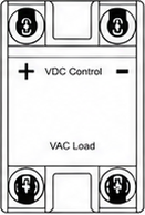
 Design with Solid State Relay 25A 250V in Cirkit Designer
Introduction
The Schneider Solid State Relay (SSR) is an electronic switching device designed to control high-power loads with precision and reliability. Unlike traditional mechanical relays, the SSR uses semiconductor components to switch circuits on or off without any moving parts. This ensures faster switching, longer lifespan, and reduced maintenance.
With a current rating of 25A and a voltage rating of 250V, this SSR is ideal for applications requiring high-power control. It is commonly used in industrial automation, HVAC systems, lighting control, and motor drives. Its compact design and robust performance make it a preferred choice for both commercial and industrial applications.
Explore Projects Built with Solid State Relay 25A 250V
 Open Project in Cirkit Designer
 Open Project in Cirkit Designer
 Open Project in Cirkit Designer
 Open Project in Cirkit Designer
Explore Projects Built with Solid State Relay 25A 250V
Open Project in Cirkit DesignerOpen Project in Cirkit DesignerOpen Project in Cirkit DesignerOpen Project in Cirkit DesignerTechnical Specifications
Below are the key technical details of the Schneider SSR:
| Parameter | Value |
|---|---|
| Manufacturer | Schneider |
| Part ID | SSR |
| Load Voltage Range | 24V AC to 250V AC |
| Load Current Rating | 25A |
| Control Voltage Range | 3V DC to 32V DC |
| Control Current | 7.5mA to 12mA |
| Switching Type | Zero-Crossing |
| Isolation Voltage | 4000V AC |
| Operating Temperature | -30°C to +80°C |
| Mounting Type | Panel Mount |
| Dimensions | 58mm x 45mm x 28mm |
Pin Configuration and Descriptions
The Schneider SSR has four terminals, as described in the table below:
| Pin Number | Label | Description |
|---|---|---|
| 1 | Input (+) | Positive terminal for the control signal (3V DC to 32V DC). |
| 2 | Input (-) | Negative terminal for the control signal (ground). |
| 3 | Load Terminal 1 | Connect to one side of the AC load circuit. |
| 4 | Load Terminal 2 | Connect to the other side of the AC load circuit and the AC power source. |
Usage Instructions
How to Use the SSR in a Circuit
Control Signal Connection:
- Connect the positive control signal (3V DC to 32V DC) to the
Input (+)terminal. - Connect the ground of the control signal to the
Input (-)terminal.
- Connect the positive control signal (3V DC to 32V DC) to the
Load Circuit Connection:
- Connect one side of the AC load to
Load Terminal 1. - Connect the other side of the AC load to
Load Terminal 2, which is also connected to the AC power source.
- Connect one side of the AC load to
Mounting:
- Secure the SSR to a heat sink or panel using screws to ensure proper heat dissipation.
- Ensure adequate ventilation around the SSR to prevent overheating.
Power On:
- Apply the control signal to the input terminals to switch the load circuit on or off.
Important Considerations and Best Practices
- Heat Dissipation: The SSR generates heat during operation. Use a heat sink or cooling fan to maintain optimal operating temperatures.
- Load Type: Ensure the load does not exceed the SSR's rated current (25A) and voltage (250V).
- Isolation: Verify proper electrical isolation between the control and load circuits to prevent damage.
- Zero-Crossing Switching: This SSR uses zero-crossing technology, which minimizes electrical noise and extends the lifespan of connected devices.
- Fuse Protection: Use an appropriate fuse or circuit breaker to protect the SSR and the load circuit from overcurrent conditions.
Example: Connecting the SSR to an Arduino UNO
Below is an example of how to control the SSR using an Arduino UNO:
// Example: Controlling a Schneider SSR with Arduino UNO
// This code toggles the SSR on and off every 2 seconds.

const int ssrPin = 9; // Pin connected to the SSR control input

void setup() {
  pinMode(ssrPin, OUTPUT); // Set the SSR pin as an output
}

void loop() {
  digitalWrite(ssrPin, HIGH); // Turn the SSR on (activates the load)
  delay(2000);                // Wait for 2 seconds
  digitalWrite(ssrPin, LOW);  // Turn the SSR off (deactivates the load)
  delay(2000);                // Wait for 2 seconds
}
Note: Use a resistor (e.g., 330Ω) in series with the SSR control input to limit current from the Arduino pin.
Troubleshooting and FAQs
Common Issues and Solutions
SSR Does Not Switch the Load:
- Cause: Insufficient control voltage or current.
- Solution: Verify that the control signal is within the specified range (3V DC to 32V DC).
Overheating:
- Cause: Excessive load current or inadequate heat dissipation.
- Solution: Ensure the load current does not exceed 25A. Use a heat sink or cooling fan.
Load Flickering:
- Cause: Unstable control signal or noisy power supply.
- Solution: Use a stable DC power source for the control signal. Add a capacitor to filter noise.
No Isolation Between Control and Load Circuits:
- Cause: Faulty SSR or incorrect wiring.
- Solution: Check wiring and replace the SSR if necessary.
FAQs
Q: Can this SSR be used with DC loads?
A: No, this SSR is designed for AC loads only. For DC loads, use a DC-specific SSR.Q: What happens if the load exceeds 25A?
A: Exceeding the rated current can damage the SSR. Always use a fuse or circuit breaker for protection.Q: Can I use this SSR without a heat sink?
A: It is not recommended. Without proper heat dissipation, the SSR may overheat and fail.Q: Is the SSR polarity-sensitive on the load side?
A: No, the load terminals are not polarity-sensitive as the SSR is designed for AC loads.
This concludes the documentation for the Schneider Solid State Relay 25A 250V (SSR). For further assistance, refer to the manufacturer's datasheet or contact technical support.