How to Use DC Power Source: Examples, Pinouts, and Specs

 Design with DC Power Source in Cirkit Designer
Introduction
A DC Power Source is an essential electronic component that supplies a constant Direct Current (DC) voltage to a circuit or system. It is widely used in various applications such as powering electronic devices, charging batteries, and as a bench power supply for testing and development purposes. Its ability to provide a stable and regulated voltage makes it a critical component in the field of electronics.
Explore Projects Built with DC Power Source

 Open Project in Cirkit Designer
 Open Project in Cirkit Designer
 Open Project in Cirkit Designer
 Open Project in Cirkit Designer
Explore Projects Built with DC Power Source

 Open Project in Cirkit Designer
 Open Project in Cirkit Designer
 Open Project in Cirkit Designer
 Open Project in Cirkit Designer
Common Applications and Use Cases
- Powering electronic circuits and systems
- Battery charging stations
- Laboratory and educational settings for experiments
- Prototyping and testing electronic components
- Robotics and automation systems
Technical Specifications
Key Technical Details
| Specification | Description |
|---|---|
| Output Voltage Range | Typically 0V to 12V, 0V to 24V, or higher |
| Output Current Range | Varies, e.g., 1A, 5A, 10A, or more depending on model |
| Power Ratings | Varies, e.g., 30W, 60W, 100W, or more |
| Regulation | Line and load regulation to maintain stable output |
| Ripple & Noise | Specified in mV peak-to-peak or RMS |
| Efficiency | Percentage of power efficiency, often >80% |
| Protection Features | Overvoltage, overcurrent, short-circuit protections |
Pin Configuration and Descriptions
| Pin/Connector | Description |
|---|---|
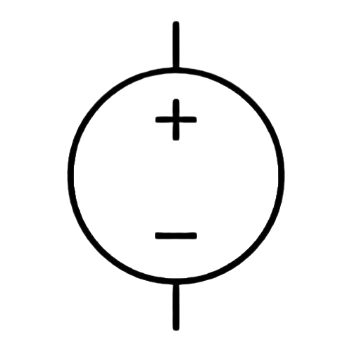
| Positive (+) | Output terminal for positive voltage supply |
| Negative (-) | Output terminal for ground or negative supply |
| Ground (⏚) | Chassis ground, for safety and noise reduction |
Usage Instructions
How to Use the Component in a Circuit
- Connect the Load: Connect the positive terminal of the DC Power Source to the positive input of your circuit and the negative terminal to the ground or negative input of your circuit.
- Set the Voltage: Adjust the voltage output knob to the desired level, ensuring it matches the voltage requirements of your circuit.
- Set the Current Limit: If available, set the current limit to prevent overcurrent conditions that could damage your circuit.
- Power On: Turn on the DC Power Source. Monitor the voltage and current to ensure they are within the desired range.
Important Considerations and Best Practices
- Voltage and Current Ratings: Never exceed the maximum voltage and current ratings of the DC Power Source or the components in your circuit.
- Polarity: Ensure correct polarity when connecting the power source to prevent damage.
- Cooling: Provide adequate ventilation around the power source to prevent overheating.
- Safety: Use proper safety equipment and procedures to prevent electric shock or short circuits.
Troubleshooting and FAQs
Common Issues
- No Output Voltage: Ensure the power source is turned on and the output terminals are properly connected. Check the fuse or circuit breaker if applicable.
- Incorrect Voltage: Verify the voltage setting and adjust if necessary. Check for proper calibration if the output is consistently off.
- Overcurrent Shutdown: Reduce the load on the power source or increase the current limit setting if it's too low.
Solutions and Tips for Troubleshooting
- Check Connections: Loose or poor connections can cause various issues. Ensure all connections are secure.
- Verify Settings: Double-check the voltage and current settings on the power source.
- Inspect Components: Look for signs of damage or overheating in your circuit components.
FAQs
Q: Can I use a DC Power Source to power an AC device? A: No, a DC Power Source provides DC voltage and cannot be used to power devices that require AC voltage.
Q: How do I know if my DC Power Source can handle my circuit's power requirements? A: Calculate the total power consumption of your circuit and ensure it does not exceed the power rating of the DC Power Source.
Q: What should I do if the power source overheats? A: Turn off the power source immediately and allow it to cool down. Ensure proper ventilation and check if the current load exceeds the power source's capability.
Example Connection with Arduino UNO
// No specific code is required for a DC Power Source as it is a power supply unit.
// However, ensure that the Arduino UNO is powered with the correct voltage.

// Connect the positive terminal of the DC Power Source to the Vin pin of the Arduino UNO
// Connect the negative terminal of the DC Power Source to one of the GND pins on the Arduino UNO

void setup() {
  // Initialize digital pin LED_BUILTIN as an output.
  pinMode(LED_BUILTIN, OUTPUT);
}

void loop() {
  // Turn the LED on (HIGH is the voltage level)
  digitalWrite(LED_BUILTIN, HIGH);
  // Wait for a second
  delay(1000);
  // Turn the LED off by making the voltage LOW
  digitalWrite(LED_BUILTIN, LOW);
   // Wait for a second
  delay(1000);
}
Note: The above code is a simple blink program for Arduino UNO, which is powered by the DC Power Source. Ensure that the voltage supplied to the Arduino UNO does not exceed its recommended input voltage (typically 7-12V for the Vin pin).