How to Use OV7725: Examples, Pinouts, and Specs
Introduction
The OV7725 is a low-voltage CMOS image sensor that provides the full functionality of a single-chip VGA camera and image processor in a small footprint package. Manufactured by OmniVision, this sensor is capable of operating at up to 60 frames per second (fps) in VGA resolution with complete user control over image quality, formatting, and output data transfer. It is widely used in various applications, including digital cameras, security cameras, machine vision, and automotive systems.
Explore Projects Built with OV7725
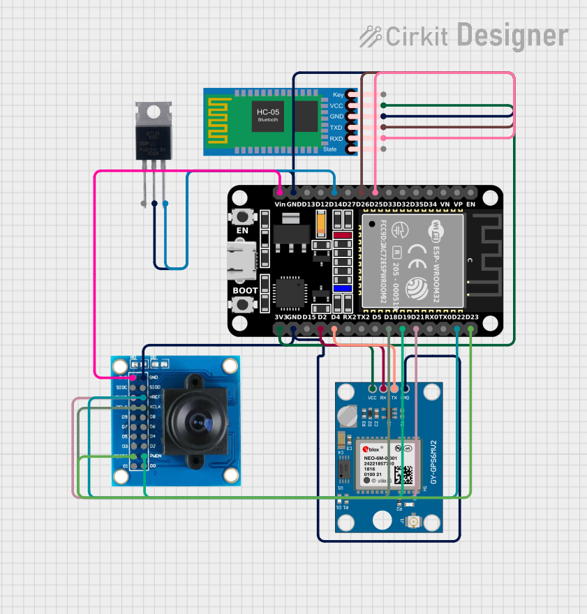
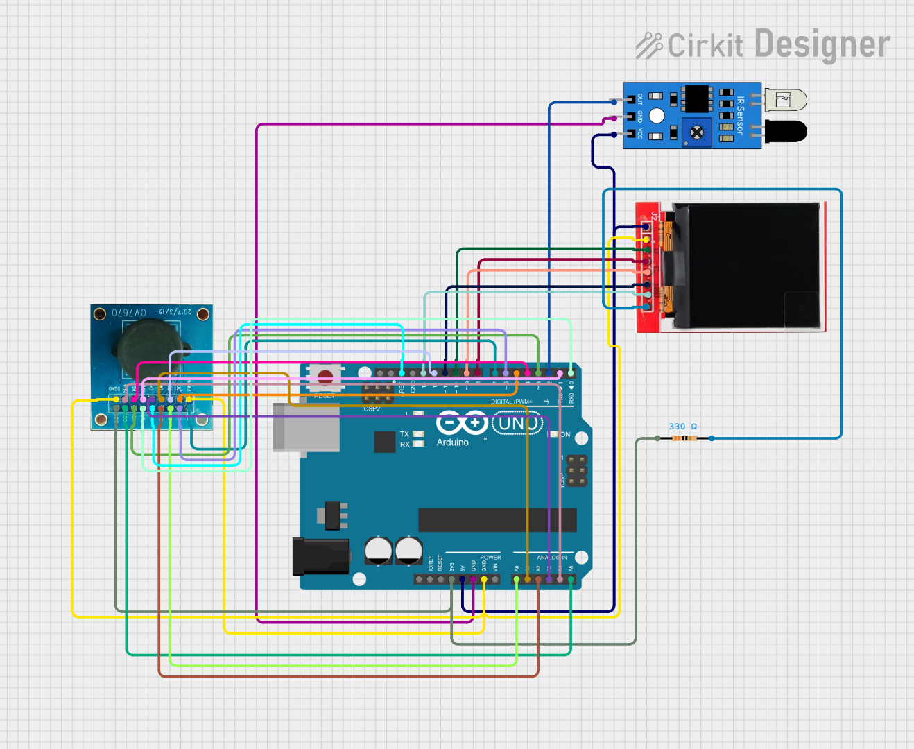


Explore Projects Built with OV7725
Common Applications and Use Cases
- Digital video cameras
- Surveillance and security systems
- Robotics and machine vision
- Automotive and industrial imaging
- Video conferencing and webcam modules
Technical Specifications
Key Technical Details
- Array Size: VGA 640 x 480
- Power Supply: Core: 1.5VDC ±5%, Analog: 2.45V to 3.0V, I/O: 1.7V to 3.0V
- Power Consumption: 60 mW typical
- Operating Temperature: -30°C to +70°C
- Output Formats: YUV/YCbCr4:2:2, RGB565/555/444, CCIR656, RAW RGB, GRB4:2:2, RGB Bayer
- Frame Rate: 60 fps at VGA, 120 fps at QVGA
- Lens Size: 1/4 inch
- Shutter Type: Electronic rolling shutter
- Dynamic Range: 50 dB typical
- Signal to Noise Ratio: 46 dB typical
Pin Configuration and Descriptions
| Pin Number | Name | Type | Description |
|---|---|---|---|
| 1 | VDD | Power | Digital core power supply (1.5V) |
| 2 | GND | Ground | Ground connection |
| 3 | DOVDD | Power | Digital I/O power supply (1.7V to 3.0V) |
| 4 | VAA | Power | Analog power supply (2.45V to 3.0V) |
| 5 | VAGND | Ground | Analog ground connection |
| 6-13 | D7-D0 | Data | Digital video port data outputs |
| 14 | PCLK | Output | Pixel clock output |
| 15 | HREF | Output | Horizontal reference signal for data output |
| 16 | VSYNC | Output | Vertical sync output |
| 17 | SIO-C | I/O | Serial camera control bus clock |
| 18 | SIO-D | I/O | Serial camera control bus data |
| 19 | RESETB | Input | Active low reset signal |
| 20 | PWDN | Input | Power down mode select |
| 21 | FREX | Input | Frame exposure control input |
| 22 | STROBE | Output | Flash strobe output |
| 23 | GPIO1 | I/O | General purpose I/O |
| 24 | GPIO0 | I/O | General purpose I/O |
Usage Instructions
How to Use the OV7725 in a Circuit
Power Supply: Connect the VDD pin to a 1.5V power supply, VAA to a 2.45V to 3.0V power supply, and DOVDD to a 1.7V to 3.0V power supply. Ensure that all grounds (GND, VAGND) are connected to the system ground.
Data Interface: Connect the D7-D0 pins to your microcontroller or processor's data input pins. The PCLK, HREF, and VSYNC pins are used to synchronize the data.
Control Interface: Use the SIO-C and SIO-D pins for serial communication to configure the sensor settings. The RESETB pin can be used to reset the sensor, and the PWDN pin can control the power-down mode.
Additional Features: The FREX and STROBE pins can be used for advanced control over exposure and flash synchronization, while GPIO0 and GPIO1 can be configured for various functions as needed.
Important Considerations and Best Practices
- Ensure that the power supply is clean and stable to prevent image corruption.
- Use proper decoupling capacitors close to the power pins to minimize power supply noise.
- Configure the sensor's registers according to the desired output format and frame rate.
- Pay attention to the timing requirements for the data interface to ensure reliable data transfer.
- Implement proper ESD protection, especially if the sensor is exposed to an environment where ESD events are likely.
Troubleshooting and FAQs
Common Issues Users Might Face
- No Image Output: Check power supplies, ensure proper reset sequence, and verify that the sensor configuration is correct.
- Corrupted Image: Ensure stable power supply, check for proper grounding, and verify the integrity of the data interface connections.
- Intermittent Operation: Check for loose connections, inspect for potential ESD damage, and ensure that the operating temperature is within specified limits.
Solutions and Tips for Troubleshooting
- Double-check all connections and ensure that solder joints are solid and free of shorts or opens.
- Use an oscilloscope to verify the clock signals (PCLK, HREF, VSYNC) and data outputs (D7-D0).
- Review the sensor's register settings to confirm they match the desired configuration.
- If using with an Arduino UNO or similar microcontroller, ensure that the library and driver for the OV7725 are correctly installed and configured.
FAQs
Q: Can the OV7725 be used in low-light conditions? A: The OV7725 performs well in a variety of lighting conditions, but for low-light performance, additional lighting or an IR illuminator may be necessary.
Q: What is the maximum frame rate of the OV7725? A: The OV7725 can operate at up to 60 fps in VGA resolution and up to 120 fps in QVGA resolution.
Q: How do I configure the OV7725 for different output formats? A: Configuration is done through the serial camera control bus (SCCB) interface by writing to the sensor's registers. Refer to the datasheet for detailed register information.
Q: Is the OV7725 compatible with Arduino? A: Yes, the OV7725 can be interfaced with an Arduino, but it requires careful timing and control via the SCCB interface. Libraries and shields are available to facilitate this connection.
Example Arduino Code
Below is an example of initializing the OV7725 with an Arduino UNO. This code assumes the use of a compatible library for the OV7725.
#include <OV7725.h>

// Create an instance of the OV7725 camera
OV7725 camera;

void setup() {
  // Initialize serial communication
  Serial.begin(9600);

  // Initialize the camera
  if (!camera.begin()) {
    Serial.println("Camera initialization failed!");
    while (1);
  }

  // Configure the camera settings
  camera.setImageSize(OV7725::VGA);
  camera.setFrameRate(OV7725::FRAMERATE_60FPS);
  camera.setColorSpace(OV7725::YUV422);

  Serial.println("Camera initialized successfully.");
}

void loop() {
  // Capture and process image frames
  // ...
}
Please note that this code is for illustrative purposes only and may require additional setup and configuration depending on the specific hardware and library used. Always refer to the library's documentation for detailed instructions and examples.