How to Use SCD41 : Examples, Pinouts, and Specs
Introduction
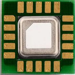
The SCD41 is a high-precision digital sensor manufactured by Sensirion (Part ID: SCD41-D-R2). It is designed to measure carbon dioxide (CO2) concentration, temperature, and humidity. The sensor leverages non-dispersive infrared (NDIR) technology for CO2 detection, ensuring accurate and reliable performance. Its compact design and low power consumption make it ideal for a wide range of applications.
Explore Projects Built with SCD41

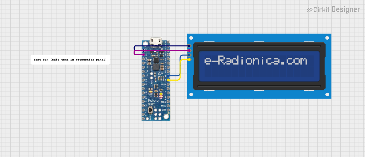
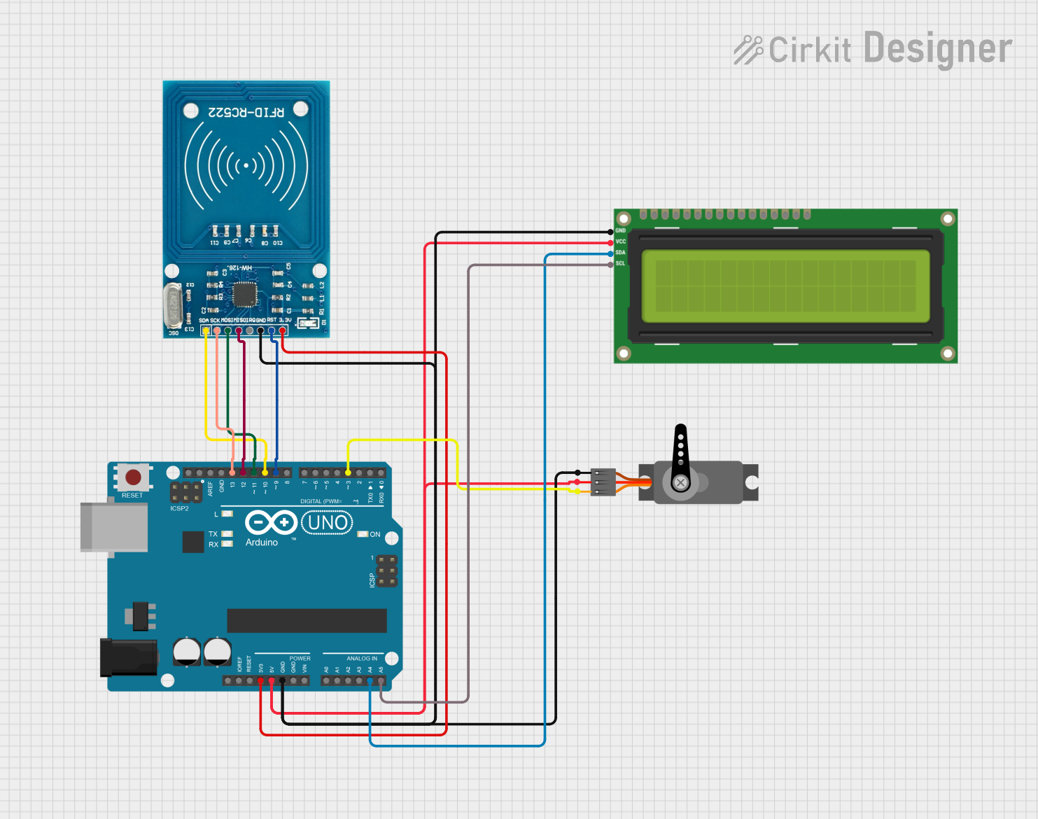

Explore Projects Built with SCD41
Common Applications
- Indoor air quality monitoring
- HVAC (Heating, Ventilation, and Air Conditioning) systems
- Smart home devices
- Environmental monitoring
- Greenhouse and agricultural control systems
Technical Specifications
Key Specifications
| Parameter | Value |
|---|---|
| CO2 Measurement Range | 400 ppm to 5000 ppm |
| CO2 Accuracy | ±(40 ppm + 5% of reading) |
| Temperature Range | -10°C to 60°C |
| Temperature Accuracy | ±0.8°C |
| Humidity Range | 0% RH to 100% RH |
| Humidity Accuracy | ±5% RH |
| Supply Voltage | 2.4 V to 5.5 V |
| Average Current Consumption | 2 mA (typical) |
| Interface | I²C |
| Dimensions | 10.1 mm × 10.1 mm × 6.5 mm |
Pin Configuration
The SCD41 sensor has a total of 8 pins. Below is the pinout description:
| Pin Number | Name | Description |
|---|---|---|
| 1 | VDD | Power supply (2.4 V to 5.5 V) |
| 2 | GND | Ground |
| 3 | SDA | I²C data line |
| 4 | SCL | I²C clock line |
| 5 | SEL | Address selection (connect to GND for default) |
| 6 | NC | Not connected (leave floating) |
| 7 | NC | Not connected (leave floating) |
| 8 | RST | Reset pin (active low, optional) |
Usage Instructions
How to Use the SCD41 in a Circuit
- Power Supply: Connect the VDD pin to a 3.3 V or 5 V power source and the GND pin to ground.
- I²C Communication: Connect the SDA and SCL pins to the corresponding I²C pins on your microcontroller. Use pull-up resistors (typically 4.7 kΩ) on both lines if not already present.
- Address Selection: The SEL pin determines the I²C address. Connect it to GND for the default address (0x62).
- Optional Reset: The RST pin can be used to reset the sensor. If unused, leave it floating.
Best Practices
- Ensure proper decoupling by placing a 100 nF capacitor close to the VDD pin.
- Avoid placing the sensor near heat sources or in direct sunlight to prevent measurement inaccuracies.
- Allow the sensor to warm up for at least 5 seconds after power-up for accurate readings.
Example: Using the SCD41 with Arduino UNO
Below is an example of how to interface the SCD41 with an Arduino UNO using the I²C protocol. This example uses the Sensirion SCD4x library, which can be installed via the Arduino Library Manager.
#include <Wire.h>
#include <SensirionI2CScd4x.h>

SensirionI2CScd4x scd4x;

void setup() {
  Wire.begin(); // Initialize I²C communication
  Serial.begin(9600); // Start serial communication for debugging

  scd4x.begin(Wire); // Initialize the SCD41 sensor
  uint16_t error;

  // Start periodic measurement
  error = scd4x.startPeriodicMeasurement();
  if (error) {
    Serial.print("Error starting measurement: ");
    Serial.println(error);
  } else {
    Serial.println("SCD41 measurement started.");
  }
}

void loop() {
  uint16_t co2;
  float temperature, humidity;
  uint16_t error;

  // Read measurement data
  error = scd4x.readMeasurement(co2, temperature, humidity);
  if (error) {
    Serial.print("Error reading measurement: ");
    Serial.println(error);
  } else if (co2 != 0) { // Check if valid data is available
    Serial.print("CO2: ");
    Serial.print(co2);
    Serial.print(" ppm, Temperature: ");
    Serial.print(temperature);
    Serial.print(" °C, Humidity: ");
    Serial.print(humidity);
    Serial.println(" %RH");
  }

  delay(5000); // Wait 5 seconds before the next reading
}
Notes
- Install the SensirionI2CScd4x library from the Arduino Library Manager before running the code.
- Ensure the I²C pull-up resistors are properly connected.
Troubleshooting and FAQs
Common Issues
No I²C Communication:
- Ensure the SDA and SCL lines are correctly connected to the microcontroller.
- Verify that pull-up resistors are present on the I²C lines.
- Check the I²C address (default: 0x62) and ensure no address conflicts.
Inaccurate Readings:
- Allow the sensor to stabilize for at least 5 seconds after power-up.
- Avoid placing the sensor in areas with high airflow or near heat sources.
Sensor Not Detected:
- Verify the power supply voltage (2.4 V to 5.5 V).
- Check the connections for loose wires or incorrect pin assignments.
FAQs
Q: Can the SCD41 measure CO2 levels below 400 ppm?
A: No, the SCD41 is designed to measure CO2 concentrations in the range of 400 ppm to 5000 ppm.
Q: How often should I calibrate the sensor?
A: The SCD41 features automatic self-calibration. However, for best results, expose the sensor to fresh air (400 ppm CO2) periodically.
Q: Can I use the SCD41 with a 3.3 V microcontroller?
A: Yes, the SCD41 operates with supply voltages between 2.4 V and 5.5 V, making it compatible with both 3.3 V and 5 V systems.
Q: What is the warm-up time for the sensor?
A: The sensor requires a warm-up time of approximately 5 seconds after power-up for accurate measurements.