Cirkit Designer Logo
Cirkit Designer
Your all-in-one circuit design IDE
Home / 
Component Documentation

How to Use Switching Power Supply: Examples, Pinouts, and Specs

Image of Switching Power Supply
Cirkit Designer LogoDesign with Switching Power Supply in Cirkit Designer

Introduction

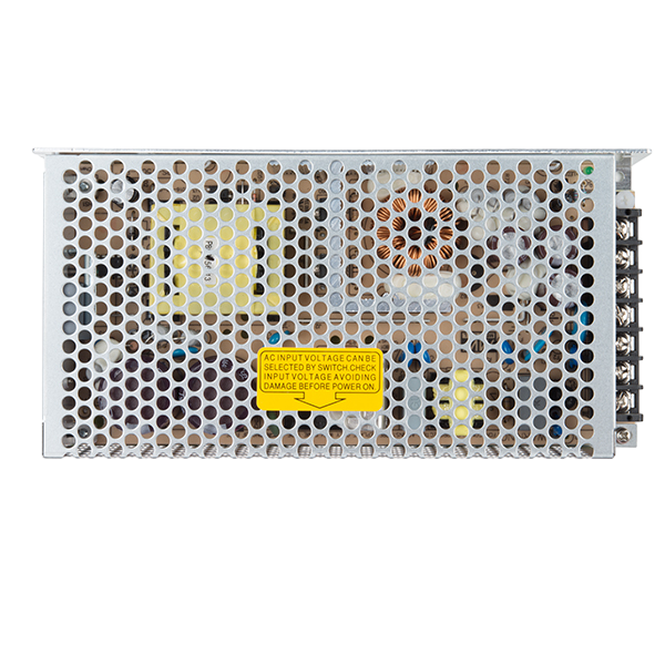
A switching power supply is an essential component in modern electronics, providing efficient power conversion from one voltage level to another. It operates by rapidly switching the current on and off, which allows for a controlled and efficient transfer of electrical power. This type of power supply is known for its efficiency, compact size, and lighter weight compared to traditional linear power supplies.

Explore Projects Built with Switching Power Supply

Use Cirkit Designer to design, explore, and prototype these projects online. Some projects support real-time simulation. Click "Open Project" to start designing instantly!
AC to DC Power Supply with Transformer and Bridge Rectifier
Image of BRIDGE RECTIFIER: A project utilizing Switching Power Supply in a practical application
This circuit is a basic AC to DC power supply that steps down 220V AC to a lower voltage using a transformer, rectifies it to DC using a bridge rectifier made of diodes, and smooths the output with an electrolytic capacitor. A rocker switch is used to turn the power supply on and off.
Cirkit Designer LogoOpen Project in Cirkit Designer
12V UPS System with Dual 18650 Li-ion Battery Backup and Voltage Regulation
Image of Power supply: A project utilizing Switching Power Supply in a practical application
This circuit is designed to provide an uninterruptible power supply (UPS) system with a 12V DC output. It includes a 12V 5A power supply connected to an AC source through a toggle switch, which charges a pair of 18650 Li-ion batteries via a voltage regulator (XL4016). The UPS module ensures a continuous power supply to the load by switching between the power supply and the battery bank.
Cirkit Designer LogoOpen Project in Cirkit Designer
Battery-Powered UPS with Step-Down Buck Converter and BMS
Image of Mini ups: A project utilizing Switching Power Supply in a practical application
This circuit is a power management system that steps down a 240V AC input to a lower DC voltage using a buck converter, which then powers a 40W UPS. The UPS is controlled by a rocker switch and is backed up by a battery management system (BMS) connected to three 3.7V batteries in series, ensuring continuous power supply.
Cirkit Designer LogoOpen Project in Cirkit Designer
Dual 5V Power Supply Distribution Circuit with Toggle Switch Control
Image of rfdriver: A project utilizing Switching Power Supply in a practical application
This circuit consists of two 5V 5A power supplies connected to an AC wall plug point, providing DC output through a 12-way connector. The ground connections from both power supplies are interconnected and also connected to the ground pins of two toggle switches. The DC outputs from the power supplies are separately connected to different pins on the 12-way connector, with each power supply output being switchable via one of the toggle switches.
Cirkit Designer LogoOpen Project in Cirkit Designer

Explore Projects Built with Switching Power Supply

Use Cirkit Designer to design, explore, and prototype these projects online. Some projects support real-time simulation. Click "Open Project" to start designing instantly!
Image of BRIDGE RECTIFIER: A project utilizing Switching Power Supply in a practical application
AC to DC Power Supply with Transformer and Bridge Rectifier
This circuit is a basic AC to DC power supply that steps down 220V AC to a lower voltage using a transformer, rectifies it to DC using a bridge rectifier made of diodes, and smooths the output with an electrolytic capacitor. A rocker switch is used to turn the power supply on and off.
Cirkit Designer LogoOpen Project in Cirkit Designer
Image of Power supply: A project utilizing Switching Power Supply in a practical application
12V UPS System with Dual 18650 Li-ion Battery Backup and Voltage Regulation
This circuit is designed to provide an uninterruptible power supply (UPS) system with a 12V DC output. It includes a 12V 5A power supply connected to an AC source through a toggle switch, which charges a pair of 18650 Li-ion batteries via a voltage regulator (XL4016). The UPS module ensures a continuous power supply to the load by switching between the power supply and the battery bank.
Cirkit Designer LogoOpen Project in Cirkit Designer
Image of Mini ups: A project utilizing Switching Power Supply in a practical application
Battery-Powered UPS with Step-Down Buck Converter and BMS
This circuit is a power management system that steps down a 240V AC input to a lower DC voltage using a buck converter, which then powers a 40W UPS. The UPS is controlled by a rocker switch and is backed up by a battery management system (BMS) connected to three 3.7V batteries in series, ensuring continuous power supply.
Cirkit Designer LogoOpen Project in Cirkit Designer
Image of rfdriver: A project utilizing Switching Power Supply in a practical application
Dual 5V Power Supply Distribution Circuit with Toggle Switch Control
This circuit consists of two 5V 5A power supplies connected to an AC wall plug point, providing DC output through a 12-way connector. The ground connections from both power supplies are interconnected and also connected to the ground pins of two toggle switches. The DC outputs from the power supplies are separately connected to different pins on the 12-way connector, with each power supply output being switchable via one of the toggle switches.
Cirkit Designer LogoOpen Project in Cirkit Designer

Common Applications and Use Cases

  • Computer and server power supplies
  • Consumer electronics (TVs, gaming consoles)
  • Industrial control systems
  • LED lighting
  • Telecommunications equipment
  • Battery chargers

Technical Specifications

The Mean Well 12V DC switching power supply is a reliable and efficient source for your power needs. Below are the key technical details and pin configuration for this component.

Key Technical Details

Specification Value
Input Voltage 85 - 264 VAC
Output Voltage 12 VDC
Output Current Up to X Amps
Frequency 47 - 63 Hz
Efficiency Up to XX%
Operating Temperature -20°C to +60°C
Safety Standards UL, CE, etc.
Dimensions XX x XX x XX mm

Note: Replace 'X' and 'XX' with actual values from the manufacturer's datasheet.

Pin Configuration and Descriptions

Pin Number Description
1 AC Line Input (L)
2 AC Neutral Input (N)
3 Ground (⏚)
4 DC Output Positive (+)
5 DC Output Negative (-)

Usage Instructions

How to Use the Component in a Circuit

  1. Connecting Input Power:

    • Connect the AC line input to pin 1 and the AC neutral input to pin 2.
    • Ensure proper grounding by connecting pin 3 to the earth ground.
  2. Connecting Output Power:

    • Connect your load to the positive output (pin 4) and negative output (pin 5).
    • Ensure that the load does not exceed the rated output current of the power supply.

Important Considerations and Best Practices

  • Always verify input voltage compatibility before powering the device.
  • Do not exceed the maximum rated output current to prevent overheating and potential damage.
  • Ensure proper ventilation around the power supply for cooling.
  • Use appropriate wire gauge for AC input and DC output to handle the current without excessive voltage drop.

Troubleshooting and FAQs

Common Issues

  • Power Supply Does Not Start:

    • Check if the AC input voltage is within the specified range.
    • Verify that the connections to pins 1 and 2 are secure and correct.
  • Output Voltage is Unstable or Incorrect:

    • Ensure that the load does not exceed the power supply's maximum rated current.
    • Check for any short circuits or overloads in the connected load.

Solutions and Tips for Troubleshooting

  • If the power supply overheats, check for adequate ventilation and reduce the load if necessary.
  • For noise-sensitive applications, consider adding additional filtering on the DC output.

FAQs

  • Q: Can this power supply be used with an Arduino UNO?

    • A: Yes, it can power an Arduino UNO as long as the output voltage is regulated to a suitable level for the Arduino (typically 5V or 3.3V).
  • Q: What is the warranty period for this Mean Well power supply?

    • A: The warranty period can vary. Please refer to the manufacturer's documentation for warranty information.

Example Arduino Connection

// Example code to demonstrate how to power an Arduino UNO with a 12V Mean Well Switching Power Supply

void setup() {
  // Initialize digital pin LED_BUILTIN as an output.
  pinMode(LED_BUILTIN, OUTPUT);
}

void loop() {
  // Turn the LED on (HIGH is the voltage level)
  digitalWrite(LED_BUILTIN, HIGH);
  // Wait for a second
  delay(1000);
  // Turn the LED off by making the voltage LOW
  digitalWrite(LED_BUILTIN, LOW);
   // Wait for a second
  delay(1000);
}

// Note: The Arduino UNO must be connected to the power supply through a voltage regulator
// or a DC-DC converter to step down the voltage to 5V.

Note: The above code is a simple blink example and assumes that the Arduino UNO is powered correctly with a regulated 5V supply derived from the 12V output of the Mean Well Switching Power Supply.