How to Use BC547 Transistor: Examples, Pinouts, and Specs

 Design with BC547 Transistor in Cirkit Designer
Introduction
The BC547 transistor is a general-purpose NPN bipolar junction transistor (BJT) widely used in electronic circuits. It is primarily utilized for switching and amplification purposes due to its high current gain and low saturation voltage. The BC547 is commonly found in small signal amplification, low-power switching applications, and as a driver transistor in various electronic projects, including those involving microcontrollers like the Arduino UNO.
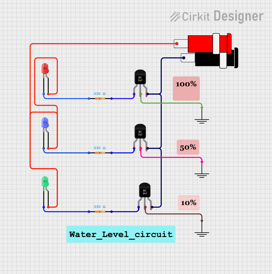
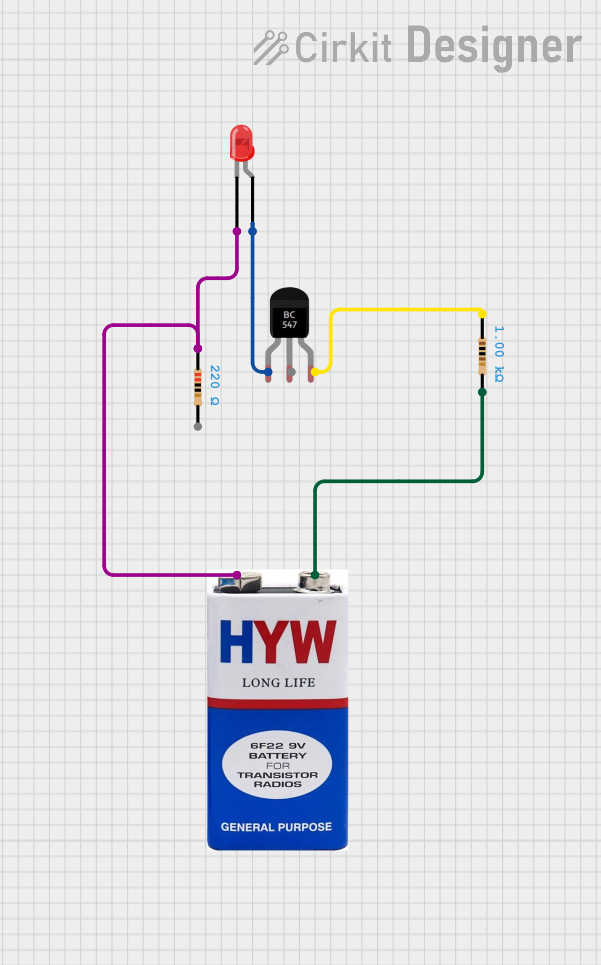
Explore Projects Built with BC547 Transistor

 Open Project in Cirkit Designer
 Open Project in Cirkit Designer
 Open Project in Cirkit Designer
 Open Project in Cirkit Designer
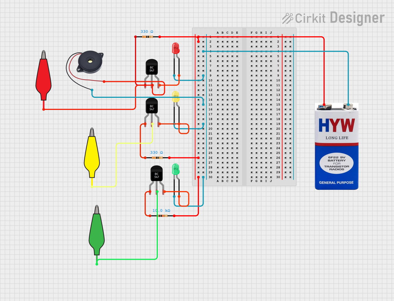
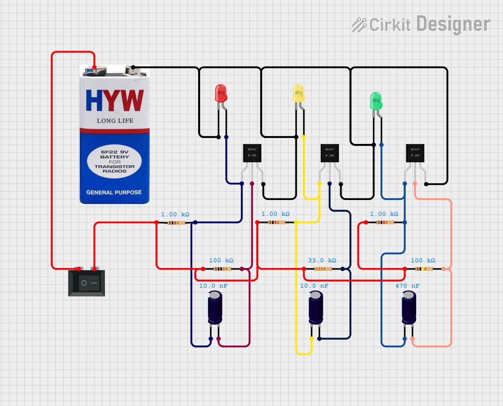
Explore Projects Built with BC547 Transistor

 Open Project in Cirkit Designer
 Open Project in Cirkit Designer
 Open Project in Cirkit Designer
 Open Project in Cirkit Designer
Technical Specifications
Key Technical Details
- Type: NPN Bipolar Junction Transistor (BJT)
- Maximum Collector-Base Voltage (Vcbo): 50V
- Maximum Collector-Emitter Voltage (Vceo): 45V
- Maximum Emitter-Base Voltage (Vebo): 6V
- Collector Current (Ic): 100mA
- DC Current Gain (hFE): 110 to 800 (varies with Ic)
- Transition Frequency (fT): 300MHz
- Power Dissipation (Ptot): 625mW
Pin Configuration and Descriptions
| Pin Number | Name | Description |
|---|---|---|
| 1 | Emitter (E) | Emits electrons into the base; must be connected to ground in NPN transistors |
| 2 | Base (B) | Controls the transistor's operation; small current to base allows a larger current to flow from collector to emitter |
| 3 | Collector (C) | Collects electrons from the emitter; connected to the load and positive voltage in NPN transistors |
Usage Instructions
How to Use the BC547 in a Circuit
- Biasing the Transistor: To operate the BC547, you need to apply a small current to the base pin. This will allow a larger current to flow between the collector and emitter pins.
- Base Resistor: Always use a base resistor to limit the current to the base and protect the transistor from overcurrent.
- Load Connection: Connect the load you want to control (e.g., LED, motor) to the collector pin and the power supply.
- Emitter Grounding: The emitter should be connected to the ground of the circuit.
- Saturation and Cutoff: For switching applications, ensure the base current is sufficient to drive the transistor into saturation when turned on and low enough to be in cutoff when turned off.
Best Practices
- Avoid exceeding the maximum voltage and current ratings to prevent damage.
- Use a current limiting resistor with LEDs or other sensitive components.
- For amplification, choose a suitable biasing point and ensure the transistor operates in the active region.
- When interfacing with microcontrollers, ensure that the base current is within the GPIO pin's current driving capability.
Troubleshooting and FAQs
Common Issues
- Transistor Not Switching: Ensure the base current is adequate. Check for proper biasing and connections.
- Overheating: This could be due to excessive power dissipation. Check if the current or voltage ratings are exceeded.
- Unexpected Behavior in Circuit: Verify that the transistor is not in a partial conduction state. It should be fully on or off for switching applications.
Solutions and Tips
- Use a multimeter to check the transistor's functionality by measuring the voltages at the pins.
- Replace the transistor if you suspect it is damaged.
- Ensure that the base resistor value is calculated correctly for the desired base current.
FAQs
Q: Can I use the BC547 for power applications? A: The BC547 is designed for low-power applications. For high-power applications, consider using a power transistor.
Q: How do I calculate the base resistor value? A: Use Ohm's law: R = (V_input - V_be) / I_base, where V_input is the control voltage, V_be is the base-emitter voltage (usually 0.7V for silicon transistors), and I_base is the desired base current.
Q: What can I use instead of a BC547? A: The BC547 can be substituted with other NPN transistors like the 2N2222, provided the specifications are suitable for your application.
Example Code for Arduino UNO
Here's a simple example of how to use the BC547 transistor to switch an LED on and off with an Arduino UNO:
// Define the pin connected to the base of the transistor
const int transistorPin = 9;

void setup() {
  // Set the transistor pin as output
  pinMode(transistorPin, OUTPUT);
}

void loop() {
  // Turn on the LED (transistor in saturation)
  digitalWrite(transistorPin, HIGH);
  delay(1000); // Wait for 1 second

  // Turn off the LED (transistor in cutoff)
  digitalWrite(transistorPin, LOW);
  delay(1000); // Wait for 1 second
}
Note: Ensure you have a suitable base resistor between the Arduino pin and the base of the BC547, and the LED has a current-limiting resistor in series with the collector-emitter circuit.