Cirkit Designer Logo
Cirkit Designer
Your all-in-one circuit design IDE
Home / 
Component Documentation

How to Use Analog Temperature Sensor (NTC) (Wokwi Compatible): Examples, Pinouts, and Specs

Image of Analog Temperature Sensor (NTC) (Wokwi Compatible)
Cirkit Designer LogoDesign with Analog Temperature Sensor (NTC) (Wokwi Compatible) in Cirkit Designer

Introduction

The Analog Temperature Sensor (NTC) is a crucial component in electronics for measuring temperature. NTC stands for Negative Temperature Coefficient, which means the resistance of the sensor decreases as the temperature increases. This sensor provides a variable voltage output that is inversely proportional to the temperature. Common applications include environmental temperature monitoring, system thermal protection, and temperature regulation in consumer electronics.

Explore Projects Built with Analog Temperature Sensor (NTC) (Wokwi Compatible)

Use Cirkit Designer to design, explore, and prototype these projects online. Some projects support real-time simulation. Click "Open Project" to start designing instantly!
Battery-Powered Health Monitoring System with Nucleo WB55RG and OLED Display
Image of Pulsefex: A project utilizing Analog Temperature Sensor (NTC) (Wokwi Compatible) in a practical application
This circuit is a multi-sensor data acquisition system that uses a Nucleo WB55RG microcontroller to interface with a digital temperature sensor (TMP102), a pulse oximeter and heart-rate sensor (MAX30102), and a 0.96" OLED display via I2C. Additionally, it includes a Sim800l module for GSM communication, powered by a 3.7V LiPo battery.
Cirkit Designer LogoOpen Project in Cirkit Designer
Arduino Nano Based Temperature Sensing Circuit
Image of filtro: A project utilizing Analog Temperature Sensor (NTC) (Wokwi Compatible) in a practical application
This circuit appears to be a temperature sensing system using an NTC thermistor connected to an Arduino Nano. The NTC thermistor forms part of a voltage divider with a 100k Ohm resistor, and the resulting voltage is read by the Arduino's analog input A0. The purpose of the circuit is likely to measure temperature changes, which can be inferred from the varying resistance of the NTC with temperature.
Cirkit Designer LogoOpen Project in Cirkit Designer
Arduino UNO-Based Smart Fan Control System with Temperature Sensor and LCD Display
Image of circuit diagram: A project utilizing Analog Temperature Sensor (NTC) (Wokwi Compatible) in a practical application
This circuit is a temperature monitoring and control system using an Arduino UNO. It includes an NTC thermistor for temperature sensing, pushbuttons for user input, an I2C module for communication, and a fan controlled by a MOSFET. The system also features a buzzer for alerts and an LCD for displaying information.
Cirkit Designer LogoOpen Project in Cirkit Designer
Arduino UNO-Based Smart Temperature Monitoring System with Bluetooth and Real-Time Clock
Image of bluetooth: A project utilizing Analog Temperature Sensor (NTC) (Wokwi Compatible) in a practical application
This circuit is a temperature monitoring system that uses an Arduino UNO to read temperature data from an LM35 sensor, display the data on an LED dot display, and transmit the data via an HC-05 Bluetooth module. Additionally, it includes a DS1307 RTC module for timekeeping.
Cirkit Designer LogoOpen Project in Cirkit Designer

Explore Projects Built with Analog Temperature Sensor (NTC) (Wokwi Compatible)

Use Cirkit Designer to design, explore, and prototype these projects online. Some projects support real-time simulation. Click "Open Project" to start designing instantly!
Image of Pulsefex: A project utilizing Analog Temperature Sensor (NTC) (Wokwi Compatible) in a practical application
Battery-Powered Health Monitoring System with Nucleo WB55RG and OLED Display
This circuit is a multi-sensor data acquisition system that uses a Nucleo WB55RG microcontroller to interface with a digital temperature sensor (TMP102), a pulse oximeter and heart-rate sensor (MAX30102), and a 0.96" OLED display via I2C. Additionally, it includes a Sim800l module for GSM communication, powered by a 3.7V LiPo battery.
Cirkit Designer LogoOpen Project in Cirkit Designer
Image of filtro: A project utilizing Analog Temperature Sensor (NTC) (Wokwi Compatible) in a practical application
Arduino Nano Based Temperature Sensing Circuit
This circuit appears to be a temperature sensing system using an NTC thermistor connected to an Arduino Nano. The NTC thermistor forms part of a voltage divider with a 100k Ohm resistor, and the resulting voltage is read by the Arduino's analog input A0. The purpose of the circuit is likely to measure temperature changes, which can be inferred from the varying resistance of the NTC with temperature.
Cirkit Designer LogoOpen Project in Cirkit Designer
Image of circuit diagram: A project utilizing Analog Temperature Sensor (NTC) (Wokwi Compatible) in a practical application
Arduino UNO-Based Smart Fan Control System with Temperature Sensor and LCD Display
This circuit is a temperature monitoring and control system using an Arduino UNO. It includes an NTC thermistor for temperature sensing, pushbuttons for user input, an I2C module for communication, and a fan controlled by a MOSFET. The system also features a buzzer for alerts and an LCD for displaying information.
Cirkit Designer LogoOpen Project in Cirkit Designer
Image of bluetooth: A project utilizing Analog Temperature Sensor (NTC) (Wokwi Compatible) in a practical application
Arduino UNO-Based Smart Temperature Monitoring System with Bluetooth and Real-Time Clock
This circuit is a temperature monitoring system that uses an Arduino UNO to read temperature data from an LM35 sensor, display the data on an LED dot display, and transmit the data via an HC-05 Bluetooth module. Additionally, it includes a DS1307 RTC module for timekeeping.
Cirkit Designer LogoOpen Project in Cirkit Designer

Technical Specifications

Key Technical Details

  • Temperature Sensing Range: Typically -55°C to 125°C
  • Nominal Resistance: 10kΩ at 25°C
  • B-Constant: 3380K - 4100K (varies by model)
  • Accuracy: ±0.5°C to ±1.5°C (depending on the temperature range)
  • Response Time: 5 seconds to 30 seconds (time to stabilize within 63.2% of the final temperature value)
  • Operating Voltage: Typically 3.3V to 5V

Pin Configuration and Descriptions

Pin Number Description
1 VCC (Power Supply)
2 Signal Output (Analog)
3 GND (Ground)

Usage Instructions

Integration into a Circuit

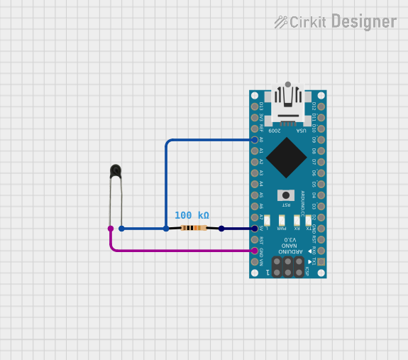
  1. Connect the VCC pin to a power supply (3.3V or 5V, depending on your system requirements).
  2. Connect the GND pin to the ground of your circuit.
  3. Connect the Signal Output pin to an analog input pin on your microcontroller (e.g., A0 on an Arduino UNO).

Important Considerations and Best Practices

  • Use a pull-up resistor if your sensor module does not have one built-in. The value of the pull-up resistor should match the nominal resistance of the NTC at the temperature of interest.
  • Keep the sensor away from heat-generating components to avoid false readings.
  • Use shielded cables for the signal output if the sensor is placed in an environment with high electrical noise.
  • Calibrate the sensor in the specific environment where it will be used for more accurate readings.

Example Code for Arduino UNO

// Include the necessary libraries
#include <math.h>

// Define the analog pin connected to the sensor
const int analogPin = A0;

// Define the value of the pull-up resistor
const float seriesResistor = 10000.0;

// Define the B-constant of the NTC
const float bConstant = 3950.0;

// Define the nominal resistance at 25 degrees Celsius
const float nominalResistance = 10000.0;

// Define the nominal temperature in Kelvin
const float nominalTemperature = 298.15;

void setup() {
  Serial.begin(9600);
}

void loop() {
  int analogValue = analogRead(analogPin);
  float resistance = (1023.0 / analogValue) - 1;
  resistance = seriesResistor / resistance;
  
  // Calculate the temperature in Kelvin
  float temperatureK = bConstant / log(resistance / nominalResistance * exp(-bConstant / nominalTemperature));
  
  // Convert Kelvin to Celsius
  float temperatureC = temperatureK - 273.15;
  
  // Print the temperature to the Serial Monitor
  Serial.print("Temperature: ");
  Serial.print(temperatureC);
  Serial.println(" C");
  
  // Wait for a second before taking the next reading
  delay(1000);
}

Troubleshooting and FAQs

Common Issues

  • Inaccurate Temperature Readings: Ensure the sensor is properly calibrated, and the pull-up resistor matches the nominal resistance.
  • No Output Signal: Check the connections and ensure the power supply is within the specified voltage range.
  • Fluctuating Readings: Minimize electrical noise by using shielded cables and keeping the sensor away from high-power components.

Solutions and Tips for Troubleshooting

  • Calibration: Use a known temperature source to calibrate the sensor output.
  • Connection Check: Verify all connections are secure and free from corrosion or damage.
  • Power Supply: Confirm the power supply is stable and within the recommended voltage range.

FAQs

Q: Can I use this sensor with a 3.3V system? A: Yes, the sensor can typically operate at 3.3V, but ensure to adjust the pull-up resistor value accordingly.

Q: How do I calibrate the sensor? A: Compare the sensor output at a known temperature (e.g., ice water at 0°C) and adjust the code or circuit as needed.

Q: What is the purpose of the B-constant? A: The B-constant is used in the Steinhart-Hart equation to calculate the temperature from the resistance of the NTC sensor. It is specific to the material of the thermistor and must be accurate for precise temperature readings.

Q: How often should I take readings from the sensor? A: It depends on your application. For stable environments, a few readings per minute may suffice. For rapidly changing temperatures, you may need readings every few seconds.