Cirkit Designer
Your all-in-one circuit design IDE
Home /
Component Documentation
How to Use Main Control Board: Examples, Pinouts, and Specs
Introduction
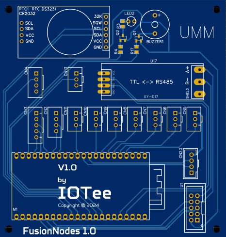
The Main Control Board by EIDOS Technologies (Part ID: FusionNodes) is a central unit designed to manage and control the functions of an electronic device or system. This board typically contains a microcontroller or microprocessor, memory, and other essential components necessary for the operation of various electronic applications.
Explore Projects Built with Main Control Board
Arduino UNO-Based Coin-Operated Communication System with LCD Display and Servo Control
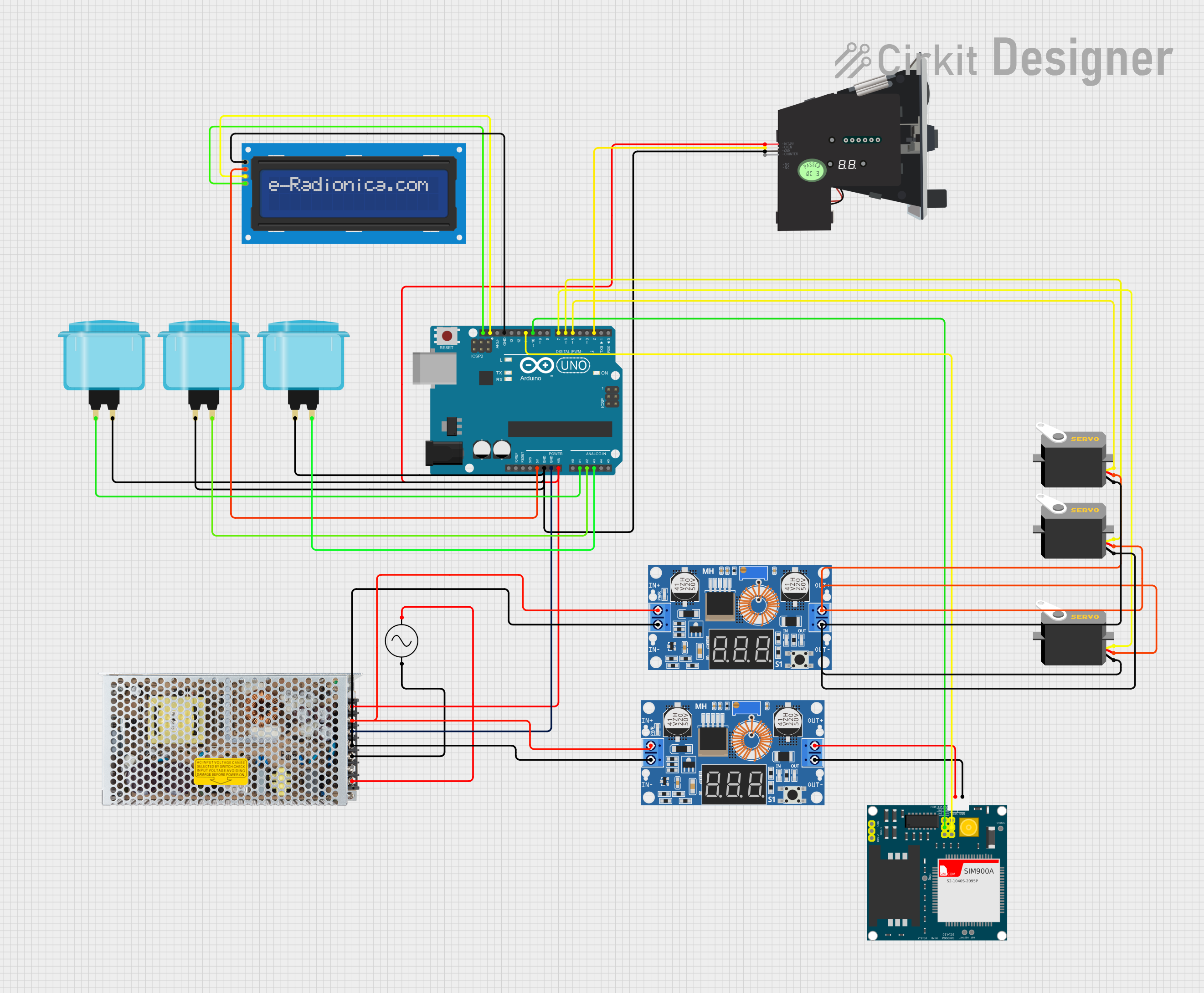
This is a microcontroller-based control system for a vending or arcade application, featuring an Arduino UNO that manages user inputs through arcade buttons, drives servos, displays information on an LCD, and communicates over GSM with the SIM900A module. Power regulation is achieved through a switching power supply and DC-DC buck converters.
Arduino Mega 2560 Controlled Motor System with LCD Display and Keypad Interface
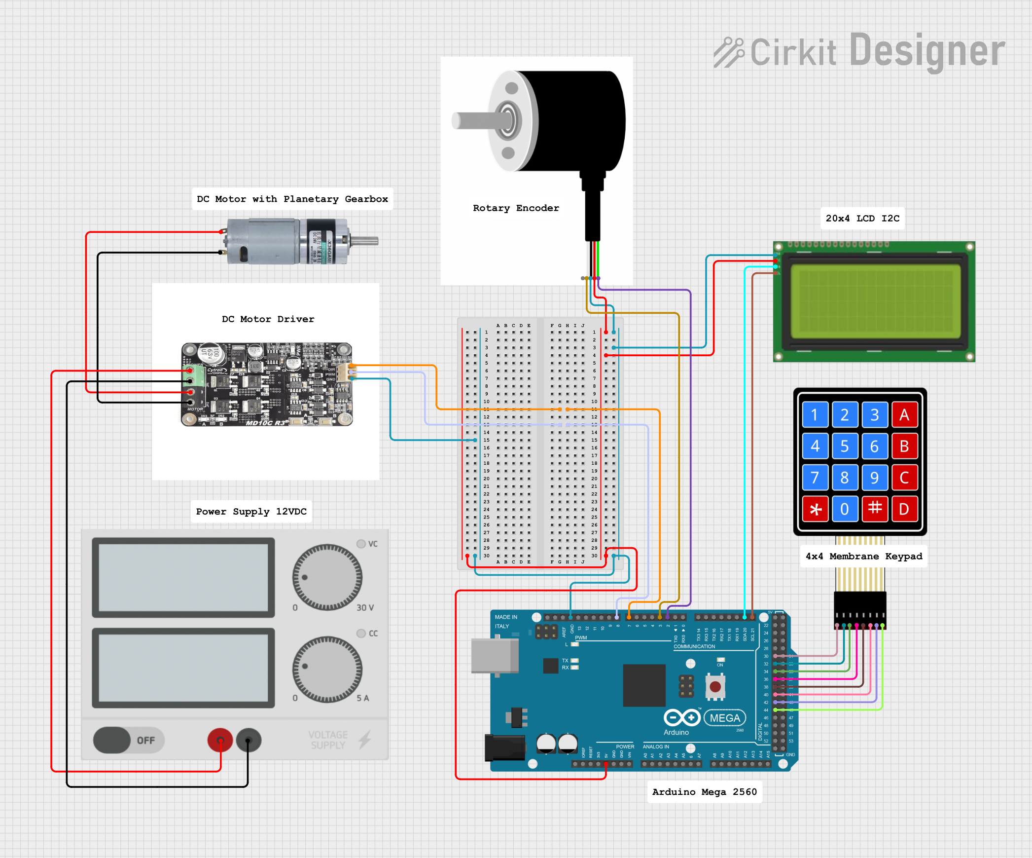
This circuit is a motor control system using an Arduino Mega 2560, which interfaces with a motor driver to control an MRB Planetary gearbox motor. It includes a rotary encoder for feedback, an LCD display for user interface, and a 4x4 membrane keypad for input, all powered by a central power supply.
Mega2560-Controlled Automation System with Non-Contact Liquid Level Sensing and Motor Control

This circuit appears to be a complex control system centered around an Arduino Mega2560 R3 Pro microcontroller, which interfaces with multiple sensors (XKC-Y26-V non-contact liquid level sensors and an LM35 temperature sensor), servo motors, a touch display, and an IBT-2 H-Bridge motor driver for controlling a planetary gearbox motor. The system also includes a UART TTL to RS485 converter for communication, likely with the touch display, and a power management subsystem with a switching power supply, fuses, and circuit breakers for safety and voltage regulation (XL4016). The absence of embedded code suggests that the functionality of the microcontroller is not defined within the provided data.
Arduino Mega 2560 Controlled Robotic System with Battery Power and Motor Drivers
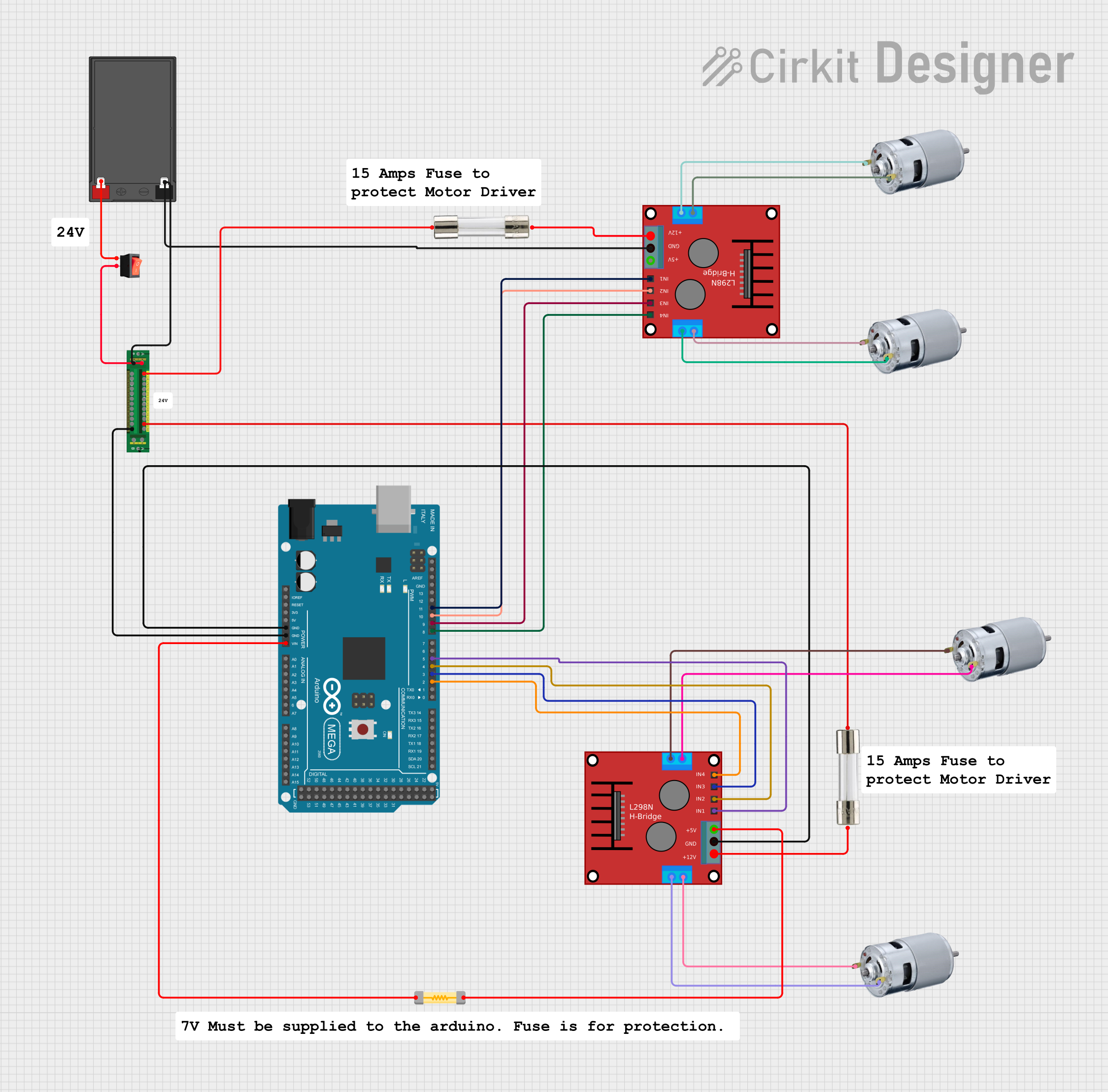
This circuit is a motor control system powered by a 12V battery, featuring an Arduino Mega 2560 microcontroller that controls multiple 775 motors through two H-bridge motor drivers. The power distribution board manages the power supply, with fuses and a rocker switch for safety and control.
Explore Projects Built with Main Control Board
Arduino UNO-Based Coin-Operated Communication System with LCD Display and Servo Control
This is a microcontroller-based control system for a vending or arcade application, featuring an Arduino UNO that manages user inputs through arcade buttons, drives servos, displays information on an LCD, and communicates over GSM with the SIM900A module. Power regulation is achieved through a switching power supply and DC-DC buck converters.
Arduino Mega 2560 Controlled Motor System with LCD Display and Keypad Interface
This circuit is a motor control system using an Arduino Mega 2560, which interfaces with a motor driver to control an MRB Planetary gearbox motor. It includes a rotary encoder for feedback, an LCD display for user interface, and a 4x4 membrane keypad for input, all powered by a central power supply.
Mega2560-Controlled Automation System with Non-Contact Liquid Level Sensing and Motor Control
This circuit appears to be a complex control system centered around an Arduino Mega2560 R3 Pro microcontroller, which interfaces with multiple sensors (XKC-Y26-V non-contact liquid level sensors and an LM35 temperature sensor), servo motors, a touch display, and an IBT-2 H-Bridge motor driver for controlling a planetary gearbox motor. The system also includes a UART TTL to RS485 converter for communication, likely with the touch display, and a power management subsystem with a switching power supply, fuses, and circuit breakers for safety and voltage regulation (XL4016). The absence of embedded code suggests that the functionality of the microcontroller is not defined within the provided data.
Arduino Mega 2560 Controlled Robotic System with Battery Power and Motor Drivers
This circuit is a motor control system powered by a 12V battery, featuring an Arduino Mega 2560 microcontroller that controls multiple 775 motors through two H-bridge motor drivers. The power distribution board manages the power supply, with fuses and a rocker switch for safety and control.
Common Applications and Use Cases
- Home Automation Systems: Central control for smart home devices.
- Robotics: Core processing unit for robotic systems.
- IoT Devices: Management and control of Internet of Things devices.
- Industrial Automation: Control unit for automated industrial processes.
- Consumer Electronics: Central control for devices like smart TVs, washing machines, etc.
Technical Specifications
Key Technical Details
| Specification | Value |
|---|---|
| Microcontroller | ARM Cortex-M4 |
| Operating Voltage | 3.3V |
| Input Voltage | 5V (via USB) |
| Digital I/O Pins | 20 |
| Analog Input Pins | 6 |
| Flash Memory | 256 KB |
| SRAM | 64 KB |
| Clock Speed | 72 MHz |
| Communication | UART, I2C, SPI |
| Dimensions | 70mm x 55mm |
Pin Configuration and Descriptions
| Pin Number | Pin Name | Description |
|---|---|---|
| 1 | VCC | Power Supply (3.3V) |
| 2 | GND | Ground |
| 3 | D0 | Digital I/O Pin 0 |
| 4 | D1 | Digital I/O Pin 1 |
| 5 | A0 | Analog Input Pin 0 |
| 6 | A1 | Analog Input Pin 1 |
| 7 | TX | UART Transmit |
| 8 | RX | UART Receive |
| 9 | SCL | I2C Clock |
| 10 | SDA | I2C Data |
| 11 | MOSI | SPI Master Out Slave In |
| 12 | MISO | SPI Master In Slave Out |
| 13 | SCK | SPI Clock |
| 14 | RST | Reset |
| 15 | 3V3 | 3.3V Output |
| 16 | 5V | 5V Output |
| 17 | GND | Ground |
| 18 | VIN | Input Voltage (5V) |
| 19 | AREF | Analog Reference |
| 20 | IOREF | I/O Reference Voltage |
Usage Instructions
How to Use the Component in a Circuit
Power Supply:
- Connect the VCC pin to a 3.3V power source.
- Connect the GND pin to the ground of your power source.
Digital I/O:
- Use the digital pins (D0-D19) for digital input/output operations.
- Configure these pins in your code as either input or output.
Analog Inputs:
- Connect analog sensors to the analog input pins (A0-A5).
- Read the analog values in your code using the appropriate functions.
Communication:
- Use TX and RX for UART communication.
- Use SCL and SDA for I2C communication.
- Use MOSI, MISO, and SCK for SPI communication.
Important Considerations and Best Practices
- Ensure that the power supply voltage does not exceed the specified limits.
- Use appropriate pull-up or pull-down resistors for digital inputs if necessary.
- Avoid connecting high-current devices directly to the I/O pins.
- Use decoupling capacitors near the power supply pins to reduce noise.
Example Code for Arduino UNO
// Example code to read an analog sensor and control an LED

const int analogPin = A0; // Analog input pin connected to the sensor
const int ledPin = 13;    // Digital output pin connected to the LED

void setup() {
  pinMode(ledPin, OUTPUT); // Set the LED pin as an output
  Serial.begin(9600);      // Initialize serial communication at 9600 bps
}

void loop() {
  int sensorValue = analogRead(analogPin); // Read the analog sensor value
  Serial.println(sensorValue);             // Print the sensor value to the serial monitor

  if (sensorValue > 512) { // If the sensor value is greater than 512
    digitalWrite(ledPin, HIGH); // Turn on the LED
  } else {
    digitalWrite(ledPin, LOW);  // Turn off the LED
  }

  delay(100); // Wait for 100 milliseconds before the next loop
}
Troubleshooting and FAQs
Common Issues Users Might Face
Board Not Powering On:
- Solution: Check the power supply connections and ensure the voltage is within the specified range.
No Communication with Peripheral Devices:
- Solution: Verify the connections for UART, I2C, or SPI communication. Ensure the correct pins are used and the devices are properly addressed.
Analog Readings are Inaccurate:
- Solution: Ensure the analog sensors are properly connected and the reference voltage (AREF) is correctly set.
Digital I/O Pins Not Responding:
- Solution: Check the pinMode configuration in your code. Ensure the pins are set as input or output as required.
Solutions and Tips for Troubleshooting
- Check Connections: Ensure all connections are secure and correctly placed.
- Use Serial Monitor: Utilize the serial monitor for debugging and checking sensor values.
- Consult Datasheets: Refer to the datasheets of connected components for specific requirements and configurations.
- Test with Simple Code: Start with simple code examples to verify the basic functionality before integrating complex logic.
By following this documentation, users can effectively utilize the Main Control Board by EIDOS Technologies in their electronic projects, ensuring reliable and efficient performance.