
How to Use Sony's Spresense LTE Extension Board: Examples, Pinouts, and Specs
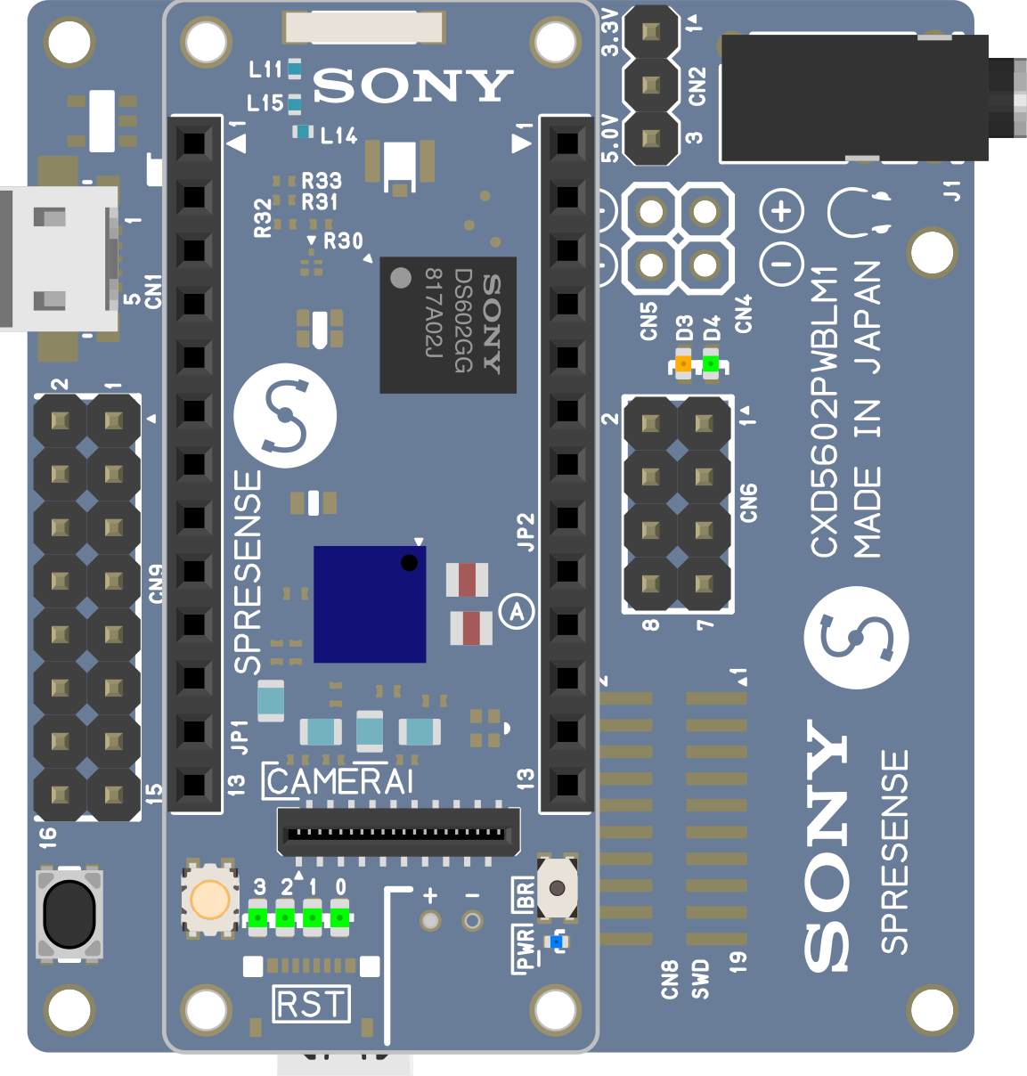
 Design with Sony's Spresense LTE Extension Board in Cirkit Designer
Introduction
The Sony Spresense LTE Extension Board (Part ID: CXD5602PWBLM1) is a hardware add-on designed to enhance the functionality of the Sony Spresense microcontroller by providing LTE connectivity. This extension board enables IoT applications to communicate over cellular networks, making it ideal for remote monitoring, asset tracking, and other applications requiring reliable wireless communication.
Explore Projects Built with Sony's Spresense LTE Extension Board
 Open Project in Cirkit Designer
 Open Project in Cirkit Designer
 Open Project in Cirkit Designer
 Open Project in Cirkit Designer
Explore Projects Built with Sony's Spresense LTE Extension Board
Open Project in Cirkit DesignerOpen Project in Cirkit DesignerOpen Project in Cirkit DesignerOpen Project in Cirkit DesignerCommon Applications and Use Cases
- IoT Devices: Enables remote data transmission for smart devices.
- Asset Tracking: Facilitates real-time location tracking over LTE networks.
- Environmental Monitoring: Collects and transmits sensor data from remote locations.
- Smart Agriculture: Supports data collection and communication in rural areas.
- Industrial Automation: Provides connectivity for machines in remote or hard-to-reach locations.
Technical Specifications
Key Technical Details
- Manufacturer: Sony
- Part ID: CXD5602PWBLM1
- Supported LTE Bands: LTE Cat-M1 and NB-IoT
- Power Supply Voltage: 3.6V to 4.2V (via battery or external power source)
- Power Consumption: Varies based on LTE activity (typically 50mA to 500mA)
- Interface: UART for communication with the Spresense main board
- SIM Card Slot: Nano-SIM
- Antenna: External LTE antenna (included)
- Dimensions: 50mm x 20mm x 5mm
- Operating Temperature: -20°C to 60°C
Pin Configuration and Descriptions
The LTE Extension Board connects to the Spresense main board via a dedicated interface. Below is the pin configuration:
| Pin Name | Description | Direction | Voltage Level |
|---|---|---|---|
| UART_TX | Transmit data to Spresense | Output | 3.3V |
| UART_RX | Receive data from Spresense | Input | 3.3V |
| VCC | Power supply input | Input | 3.6V to 4.2V |
| GND | Ground | - | 0V |
| SIM_DET | SIM card detection signal | Output | 3.3V |
| RESET | Reset signal for LTE module | Input | 3.3V |
| ANT | LTE antenna connection | - | - |
Usage Instructions
How to Use the Component in a Circuit
Connect the LTE Extension Board to the Spresense Main Board:
- Align the connectors on the LTE board with the corresponding slots on the Spresense main board.
- Secure the connection to ensure proper communication between the boards.
Insert a Nano-SIM Card:
- Place a valid Nano-SIM card into the SIM card slot on the LTE board.
- Ensure the SIM card supports LTE Cat-M1 or NB-IoT for compatibility.
Attach the LTE Antenna:
- Connect the included LTE antenna to the ANT port on the board.
- Position the antenna for optimal signal reception.
Power the Board:
- Supply power to the Spresense main board, which will also power the LTE extension board.
- Alternatively, connect an external power source to the VCC and GND pins.
Establish Communication:
- Use the UART interface to send AT commands to the LTE module for configuration and data transmission.
Important Considerations and Best Practices
- Power Supply: Ensure a stable power supply to avoid communication interruptions.
- Antenna Placement: Position the antenna away from metal objects to minimize signal interference.
- Firmware Updates: Keep the Spresense main board and LTE module firmware up to date for optimal performance.
- SIM Card Compatibility: Verify that the SIM card supports the required LTE bands and has an active data plan.
Example Code for Arduino UNO
The LTE Extension Board is typically used with the Spresense main board, but here is an example of how to send AT commands using an Arduino UNO for testing purposes:
#include <SoftwareSerial.h>

// Define RX and TX pins for SoftwareSerial
SoftwareSerial lteSerial(10, 11); // RX = pin 10, TX = pin 11

void setup() {
  // Initialize serial communication with the LTE module
  lteSerial.begin(9600); // LTE module baud rate
  Serial.begin(9600);    // Monitor baud rate

  // Send an AT command to check communication
  Serial.println("Sending AT command...");
  lteSerial.println("AT"); // Basic AT command to test communication
}

void loop() {
  // Check for data from the LTE module
  if (lteSerial.available()) {
    String response = lteSerial.readString();
    Serial.println("LTE Module Response: " + response);
  }

  // Check for user input from the Serial Monitor
  if (Serial.available()) {
    String command = Serial.readString();
    lteSerial.println(command); // Send user command to LTE module
  }
}
Notes:
- Replace
10and11with the appropriate pins if using a different microcontroller. - Ensure the LTE board is powered and connected to the Arduino's UART pins.
Troubleshooting and FAQs
Common Issues Users Might Face
No Response from the LTE Module:
- Cause: Incorrect UART connection or baud rate mismatch.
- Solution: Verify the TX and RX connections and ensure the baud rate matches the module's default setting (9600 bps).
SIM Card Not Detected:
- Cause: Improper SIM card insertion or unsupported SIM card.
- Solution: Reinsert the SIM card and ensure it supports LTE Cat-M1 or NB-IoT.
Weak or No LTE Signal:
- Cause: Poor antenna placement or network coverage issues.
- Solution: Reposition the antenna and check the network coverage in your area.
High Power Consumption:
- Cause: Continuous data transmission or poor signal strength.
- Solution: Optimize data transmission intervals and improve antenna placement.
Solutions and Tips for Troubleshooting
- Use a multimeter to check the power supply voltage.
- Test the LTE module with basic AT commands (e.g.,
AT,AT+CSQ) to verify functionality. - Refer to the Spresense LTE Extension Board user manual for advanced troubleshooting steps.
By following this documentation, users can effectively integrate the Sony Spresense LTE Extension Board into their IoT projects and leverage its LTE connectivity for a wide range of applications.