Cirkit Designer Logo
Cirkit Designer
Your all-in-one circuit design IDE
Home / 
Component Documentation

How to Use CNC Microstepper Driver - Board: Examples, Pinouts, and Specs

Image of CNC Microstepper Driver - Board
Cirkit Designer LogoDesign with CNC Microstepper Driver - Board in Cirkit Designer

Introduction

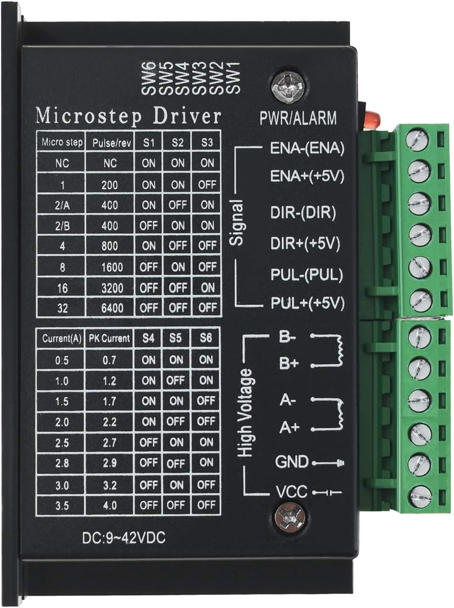
The CNC Microstepper Driver Board by Usongshine is an essential component in the realm of computer numerical control (CNC) machinery. It serves as an interface between a CNC controller and stepper motors, translating digital commands into precise motor movements. This driver board is commonly used in applications such as 3D printers, laser cutters, engraving machines, and robotic arms, where accurate positioning and motion control are critical.

Explore Projects Built with CNC Microstepper Driver - Board

Use Cirkit Designer to design, explore, and prototype these projects online. Some projects support real-time simulation. Click "Open Project" to start designing instantly!
CNC Machine Control System with Dual tb6600 Stepper Drivers and MAch3 USB Interface
Image of Jayshree CNC: A project utilizing CNC Microstepper Driver - Board in a practical application
This circuit appears to be a control system for a CNC machine or similar automated equipment. It includes two tb6600 Micro Stepping Motor Drivers for controlling stepper motors, a DC power source with a step-down buck converter to provide the necessary voltage levels, and a 4-channel relay module for switching higher power loads. The MAch3 CNC USB interface suggests the system is designed to interface with computer numerical control software, and the RMCS_3001 BLDC Driver indicates the presence of a brushless DC motor control. The Tiva C launchpad microcontroller and various connectors imply that the system is modular and may be programmable for specific automation tasks.
Cirkit Designer LogoOpen Project in Cirkit Designer
Closed Loop Stepper Motor Control System with Ethernet Smooth Stepper and Arduino Nano
Image of Queen Ant CNC Controller: A project utilizing CNC Microstepper Driver - Board in a practical application
This circuit is a CNC control system that integrates multiple power supplies, stepper motor drivers, and breakout boards to control stepper motors and other peripherals. It includes an Arduino Nano for additional control logic and an Ethernet Smooth Stepper for network connectivity, enabling precise control of CNC machinery.
Cirkit Designer LogoOpen Project in Cirkit Designer
Arduino UNO Controlled Bipolar Stepper Motor with CNC Microstepper Driver
Image of Lab5: A project utilizing CNC Microstepper Driver - Board in a practical application
This circuit controls a bipolar stepper motor using an Arduino UNO and a CNC microstepper driver board. The Arduino UNO sends control signals to the driver board, which in turn powers and drives the stepper motor. A power supply provides the necessary voltage to the driver board and the Arduino.
Cirkit Designer LogoOpen Project in Cirkit Designer
ATmega328P Microcontroller-Driven Stepper Motor with DRV8825
Image of Shutter for laser: A project utilizing CNC Microstepper Driver - Board in a practical application
This circuit is designed to control a bipolar stepper motor using a DRV8825 stepper motor driver, which is interfaced with a Nano 3.0 ATmega328P microcontroller. The microcontroller sends step and direction signals to the DRV8825, which in turn drives the stepper motor's coils. Power is supplied to the system through a 5V adapter for the logic and a DC power source for the motor, with an electrolytic capacitor for voltage smoothing on the motor supply.
Cirkit Designer LogoOpen Project in Cirkit Designer

Explore Projects Built with CNC Microstepper Driver - Board

Use Cirkit Designer to design, explore, and prototype these projects online. Some projects support real-time simulation. Click "Open Project" to start designing instantly!
Image of Jayshree CNC: A project utilizing CNC Microstepper Driver - Board in a practical application
CNC Machine Control System with Dual tb6600 Stepper Drivers and MAch3 USB Interface
This circuit appears to be a control system for a CNC machine or similar automated equipment. It includes two tb6600 Micro Stepping Motor Drivers for controlling stepper motors, a DC power source with a step-down buck converter to provide the necessary voltage levels, and a 4-channel relay module for switching higher power loads. The MAch3 CNC USB interface suggests the system is designed to interface with computer numerical control software, and the RMCS_3001 BLDC Driver indicates the presence of a brushless DC motor control. The Tiva C launchpad microcontroller and various connectors imply that the system is modular and may be programmable for specific automation tasks.
Cirkit Designer LogoOpen Project in Cirkit Designer
Image of Queen Ant CNC Controller: A project utilizing CNC Microstepper Driver - Board in a practical application
Closed Loop Stepper Motor Control System with Ethernet Smooth Stepper and Arduino Nano
This circuit is a CNC control system that integrates multiple power supplies, stepper motor drivers, and breakout boards to control stepper motors and other peripherals. It includes an Arduino Nano for additional control logic and an Ethernet Smooth Stepper for network connectivity, enabling precise control of CNC machinery.
Cirkit Designer LogoOpen Project in Cirkit Designer
Image of Lab5: A project utilizing CNC Microstepper Driver - Board in a practical application
Arduino UNO Controlled Bipolar Stepper Motor with CNC Microstepper Driver
This circuit controls a bipolar stepper motor using an Arduino UNO and a CNC microstepper driver board. The Arduino UNO sends control signals to the driver board, which in turn powers and drives the stepper motor. A power supply provides the necessary voltage to the driver board and the Arduino.
Cirkit Designer LogoOpen Project in Cirkit Designer
Image of Shutter for laser: A project utilizing CNC Microstepper Driver - Board in a practical application
ATmega328P Microcontroller-Driven Stepper Motor with DRV8825
This circuit is designed to control a bipolar stepper motor using a DRV8825 stepper motor driver, which is interfaced with a Nano 3.0 ATmega328P microcontroller. The microcontroller sends step and direction signals to the DRV8825, which in turn drives the stepper motor's coils. Power is supplied to the system through a 5V adapter for the logic and a DC power source for the motor, with an electrolytic capacitor for voltage smoothing on the motor supply.
Cirkit Designer LogoOpen Project in Cirkit Designer

Technical Specifications

General Features

  • Microstepping capabilities for smooth and precise motor control
  • Compatible with a wide range of stepper motors
  • Built-in overcurrent and thermal protection

Electrical Characteristics

  • Input Voltage: 12V-36V DC
  • Output Current: Adjustable, up to 4A per phase
  • Microstepping Resolutions: Full, 1/2, 1/4, 1/8, 1/16 step

Pin Configuration and Descriptions

Pin Number Pin Name Description
1 VDD Logic supply voltage (5V)
2 GND Ground connection
3 DIR Direction control input
4 STEP Step control input
5 ENA Enable motor output
6 VMOT Motor supply voltage (12V-36V)
7 A1 Motor coil A lead 1
8 A2 Motor coil A lead 2
9 B1 Motor coil B lead 1
10 B2 Motor coil B lead 2

Usage Instructions

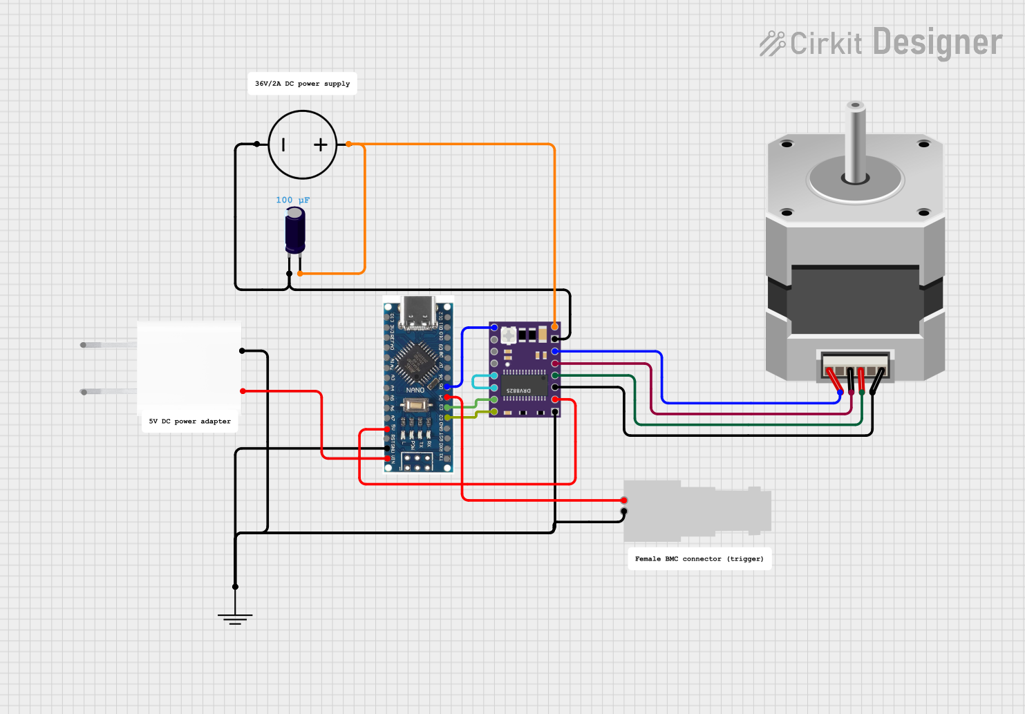
Connecting the Driver to a Stepper Motor

  1. Ensure the power supply is disconnected before making any connections.
  2. Connect the motor leads to the driver board's A1, A2, B1, and B2 pins according to the motor's datasheet.
  3. Connect the power supply to the VMOT and GND pins, ensuring the voltage is within the specified range.
  4. Connect the logic supply voltage (5V) to the VDD pin and ground to the GND pin.

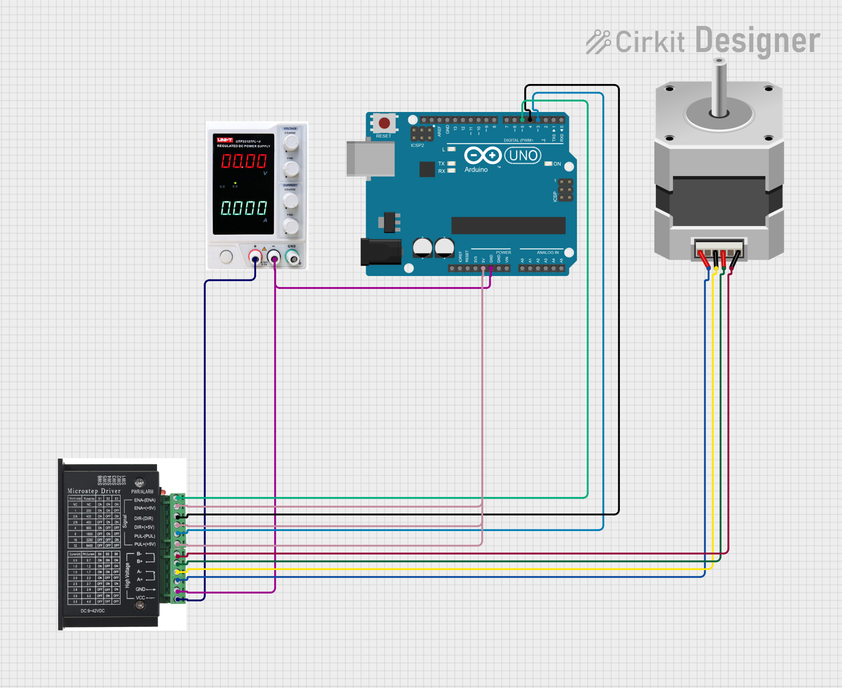
Interfacing with a CNC Controller or Arduino UNO

  1. Connect the DIR pin to the digital output pin on the controller that will determine the motor's direction.
  2. Connect the STEP pin to the digital output pin on the controller that will trigger the motor steps.
  3. Optionally, connect the ENA pin to a digital output pin if motor enable control is required.

Programming the Arduino UNO for Basic Operation

// Define the connection pins
const int dirPin = 2; // Direction pin
const int stepPin = 3; // Step pin
const int enablePin = 4; // Enable pin

void setup() {
  // Set the pin modes
  pinMode(dirPin, OUTPUT);
  pinMode(stepPin, OUTPUT);
  pinMode(enablePin, OUTPUT);

  // Enable the motor driver
  digitalWrite(enablePin, LOW);
}

void loop() {
  // Set the motor direction
  digitalWrite(dirPin, HIGH); // Set to LOW for the opposite direction

  // Move the motor with a simple stepping pattern
  for (int i = 0; i < 200; i++) {
    // Trigger one step
    digitalWrite(stepPin, HIGH);
    delayMicroseconds(1000); // Adjust the speed by changing the delay
    digitalWrite(stepPin, LOW);
    delayMicroseconds(1000);
  }

  // Pause between direction changes
  delay(1000);

  // Change direction
  digitalWrite(dirPin, LOW);

  // Repeat the stepping pattern
  for (int i = 0; i < 200; i++) {
    digitalWrite(stepPin, HIGH);
    delayMicroseconds(1000);
    digitalWrite(stepPin, LOW);
    delayMicroseconds(1000);
  }

  delay(1000); // Pause before the next loop iteration
}

Best Practices

  • Always adjust the current limit to match the specifications of the stepper motor being used.
  • Use a heatsink if the driver is expected to handle high currents for extended periods.
  • Ensure proper ventilation around the driver board to prevent overheating.

Troubleshooting and FAQs

Common Issues

  • Motor not moving: Check connections, ensure power supply is within the specified range, and verify that the motor is enabled.
  • Motor stalling or skipping steps: Adjust the current limit, check for mechanical obstructions, and ensure the motor is not overloaded.
  • Driver overheating: Ensure adequate cooling, reduce the current limit, or check for short circuits.

FAQs

Q: Can I use this driver board with any stepper motor? A: The driver board is compatible with a wide range of stepper motors, but always check the motor's voltage and current requirements to ensure compatibility.

Q: How do I adjust the current limit on the driver board? A: The current limit is typically set using a potentiometer on the board. Consult the manufacturer's documentation for the specific adjustment procedure.

Q: What is microstepping, and how do I configure it? A: Microstepping divides a full step into smaller steps for smoother motion. Configuration is usually done through jumpers or dip switches on the board.

Q: Can I control multiple stepper motors with one driver board? A: No, each stepper motor requires its own driver board for independent control.

For further assistance, consult the manufacturer's technical support or community forums dedicated to CNC and stepper motor control.