Cirkit Designer Logo
Cirkit Designer
Your all-in-one circuit design IDE
Home / 
Component Documentation

How to Use led caquita: Examples, Pinouts, and Specs


Image of led caquita
Cirkit Designer LogoDesign with led caquita in Cirkit Designer

Introduction

  • An LED (Light Emitting Diode) is a semiconductor device that emits light when an electric current flows through it. The light is produced as electrons recombine with holes within the diode, releasing energy in the form of photons.
  • LEDs are widely used in various applications, including indicator lights, displays, backlighting, and general-purpose lighting. They are valued for their energy efficiency, long lifespan, and compact size.

Explore Projects Built with led caquita
Use Cirkit Designer to design, explore, and prototype these projects online. Some projects support real-time simulation. Click "Open Project" to start designing instantly!
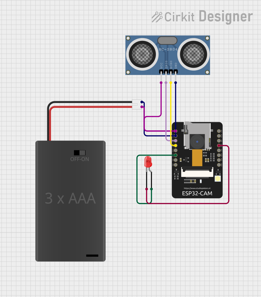
ESP32-CAM Ultrasonic Distance Sensor with QR Code Reader and LED Indicator
Image of esp-cam: A project utilizing led caquita in a practical application
This circuit features an ESP32-CAM module connected to an HC-SR04 ultrasonic distance sensor and a red LED, powered by a 3xAAA battery pack. The ESP32-CAM reads QR codes and controls the LED based on the distance measured by the ultrasonic sensor, turning the LED on if an object is detected within 10 cm.
Cirkit Designer LogoOpen Project in Cirkit Designer
Arduino Nano-Controlled Sound-Activated LED Light with Phase-Dependent Audio Feedback
Image of Clap Back 2: A project utilizing led caquita in a practical application
This circuit is designed to control a high-current LED light with sound detection and playback capabilities. An Arduino Nano is used to detect claps via a Sound Detector and toggle the LED light through a TIP120 Darlington Transistor, with different sound effects played for each phase of operation using an Adafruit Audio FX Mini Sound Board connected to a Loudspeaker. The system's behavior, including light control and sound playback, is determined by the clap frequency, with the Arduino programmed to manage the sequence of operations and phase transitions.
Cirkit Designer LogoOpen Project in Cirkit Designer
ESP32-Based Ambient Light Monitoring System with I2C LCD Display and Keypad Interface
Image of ESP roos: A project utilizing led caquita in a practical application
This circuit features an ESP32 microcontroller connected to an ambient light sensor, a 4x4 membrane matrix keypad, an I2C LCD screen, and a KY-008 laser emitter. The ESP32 reads ambient light intensity and displays it on the LCD screen, while the keypad allows user interaction to retrieve stored light intensity values from memory. The laser emitter is included in the circuit but not interfaced with the ESP32 in the provided code.
Cirkit Designer LogoOpen Project in Cirkit Designer
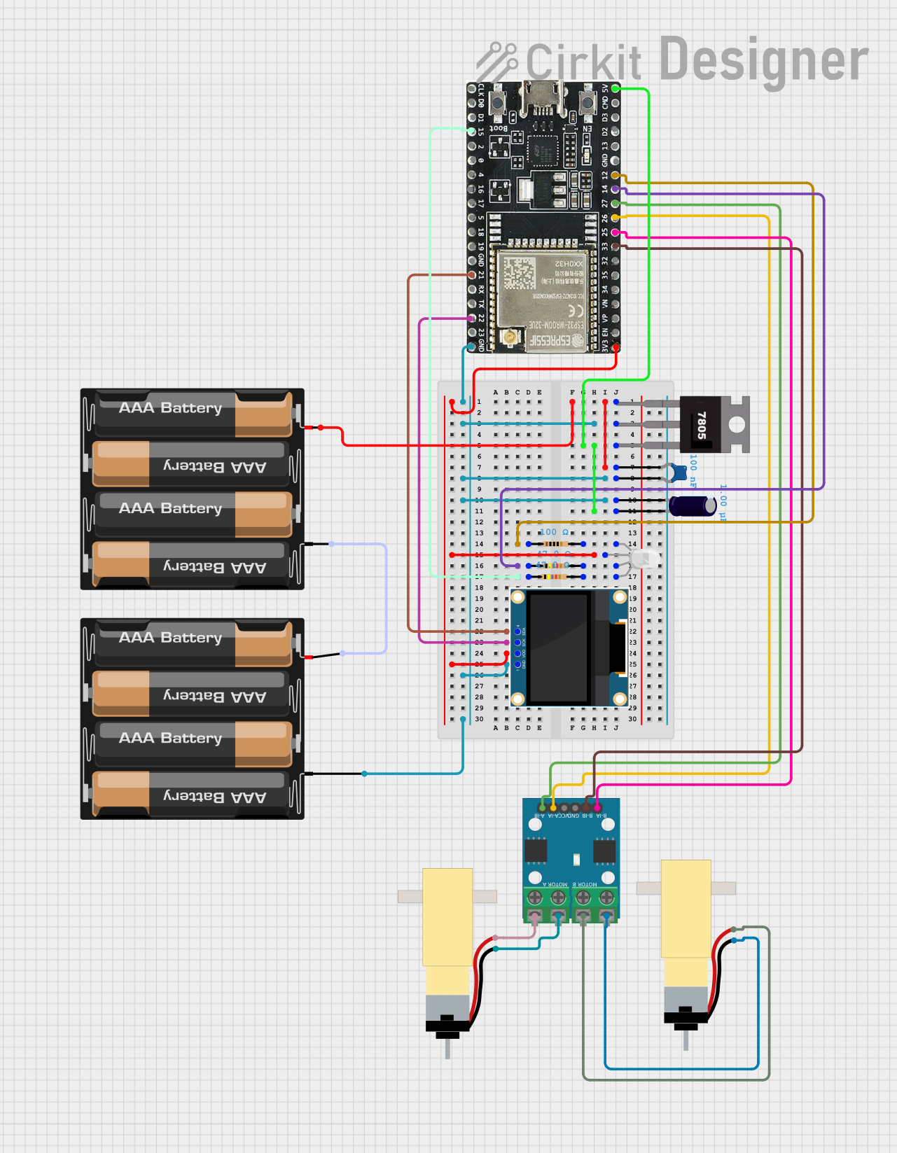
ESP32-WROOM-32UE Wi-Fi Controlled Robotic Car with OLED Display and RGB LED
Image of mkrl bot: A project utilizing led caquita in a practical application
This circuit is a WiFi-controlled robotic system powered by an ESP32 microcontroller. It features an OLED display for status messages, an RGB LED for visual feedback, and dual hobby gearmotors driven by an L9110 motor driver for movement. The system is powered by a 4 x AAA battery pack regulated to 5V using a 7805 voltage regulator.
Cirkit Designer LogoOpen Project in Cirkit Designer

Explore Projects Built with led caquita

Use Cirkit Designer to design, explore, and prototype these projects online. Some projects support real-time simulation. Click "Open Project" to start designing instantly!
Image of esp-cam: A project utilizing led caquita in a practical application
ESP32-CAM Ultrasonic Distance Sensor with QR Code Reader and LED Indicator
This circuit features an ESP32-CAM module connected to an HC-SR04 ultrasonic distance sensor and a red LED, powered by a 3xAAA battery pack. The ESP32-CAM reads QR codes and controls the LED based on the distance measured by the ultrasonic sensor, turning the LED on if an object is detected within 10 cm.
Cirkit Designer LogoOpen Project in Cirkit Designer
Image of Clap Back 2: A project utilizing led caquita in a practical application
Arduino Nano-Controlled Sound-Activated LED Light with Phase-Dependent Audio Feedback
This circuit is designed to control a high-current LED light with sound detection and playback capabilities. An Arduino Nano is used to detect claps via a Sound Detector and toggle the LED light through a TIP120 Darlington Transistor, with different sound effects played for each phase of operation using an Adafruit Audio FX Mini Sound Board connected to a Loudspeaker. The system's behavior, including light control and sound playback, is determined by the clap frequency, with the Arduino programmed to manage the sequence of operations and phase transitions.
Cirkit Designer LogoOpen Project in Cirkit Designer
Image of ESP roos: A project utilizing led caquita in a practical application
ESP32-Based Ambient Light Monitoring System with I2C LCD Display and Keypad Interface
This circuit features an ESP32 microcontroller connected to an ambient light sensor, a 4x4 membrane matrix keypad, an I2C LCD screen, and a KY-008 laser emitter. The ESP32 reads ambient light intensity and displays it on the LCD screen, while the keypad allows user interaction to retrieve stored light intensity values from memory. The laser emitter is included in the circuit but not interfaced with the ESP32 in the provided code.
Cirkit Designer LogoOpen Project in Cirkit Designer
Image of mkrl bot: A project utilizing led caquita in a practical application
ESP32-WROOM-32UE Wi-Fi Controlled Robotic Car with OLED Display and RGB LED
This circuit is a WiFi-controlled robotic system powered by an ESP32 microcontroller. It features an OLED display for status messages, an RGB LED for visual feedback, and dual hobby gearmotors driven by an L9110 motor driver for movement. The system is powered by a 4 x AAA battery pack regulated to 5V using a 7805 voltage regulator.
Cirkit Designer LogoOpen Project in Cirkit Designer

Technical Specifications

  • Forward Voltage (Vf): Typically 1.8V to 3.3V (varies by color and type)
  • Forward Current (If): 10mA to 30mA (standard LEDs)
  • Power Dissipation: Typically 30mW to 150mW
  • Viewing Angle: 20° to 120° (depending on the LED design)
  • Polarity: LEDs are polarized components with an anode (+) and cathode (-).

Pin Configuration and Descriptions

Pin Name Description Identification Method
Anode Positive terminal (+) Longer leg of the LED
Cathode Negative terminal (-) Shorter leg or flat edge on case

Usage Instructions

  1. Connecting the LED in a Circuit:

    • Always use a current-limiting resistor in series with the LED to prevent damage. The resistor value can be calculated using Ohm's Law: [ R = \frac{V_{supply} - V_f}{I_f} ] Where:
      • (V_{supply}) is the supply voltage
      • (V_f) is the forward voltage of the LED
      • (I_f) is the desired forward current (e.g., 20mA)
  2. Example Circuit:

    • For a 5V supply and an LED with (V_f = 2V) and (I_f = 20mA): [ R = \frac{5V - 2V}{0.02A} = 150\Omega ]
    • Use a 150Ω resistor in series with the LED.
  3. Using an LED with Arduino UNO:

    • Connect the anode of the LED to a digital pin (e.g., pin 13) on the Arduino through a resistor.
    • Connect the cathode to the GND pin of the Arduino.

    Sample Code:

    // Simple LED Blink Example
    // Connect the LED anode to pin 13 and cathode to GND through a resistor.
    
    const int ledPin = 13; // Pin connected to the LED
    
    void setup() {
      pinMode(ledPin, OUTPUT); // Set pin 13 as an output
    }
    
    void loop() {
      digitalWrite(ledPin, HIGH); // Turn the LED on
      delay(1000);                // Wait for 1 second
      digitalWrite(ledPin, LOW);  // Turn the LED off
      delay(1000);                // Wait for 1 second
    }
    
  4. Best Practices:

    • Always check the LED's datasheet for exact specifications.
    • Avoid exceeding the maximum forward current to prevent overheating or damage.
    • Use appropriate resistors or constant current drivers for high-power LEDs.

Troubleshooting and FAQs

Common Issues

  1. LED Does Not Light Up:

    • Cause: Incorrect polarity.

    • Solution: Ensure the anode is connected to the positive voltage and the cathode to ground.

    • Cause: No current-limiting resistor or incorrect resistor value.

    • Solution: Verify the resistor value and connections.

  2. LED Flickers or is Dim:

    • Cause: Insufficient current or unstable power supply.
    • Solution: Check the power supply voltage and ensure the resistor value allows sufficient current.
  3. LED Burns Out Quickly:

    • Cause: Excessive current.
    • Solution: Use a proper current-limiting resistor or driver circuit.

FAQs

  • Q: Can I connect an LED directly to a battery?
    A: No, always use a current-limiting resistor to prevent excessive current from damaging the LED.

  • Q: How do I identify the anode and cathode of an LED?
    A: The anode is the longer leg, and the cathode is the shorter leg or the side with a flat edge on the LED casing.

  • Q: Can I use an LED with an AC power source?
    A: LEDs are designed for DC operation. To use them with AC, you need a rectifier circuit and a current-limiting resistor.

  • Q: What happens if I reverse the polarity of an LED?
    A: The LED will not light up, but it typically won't be damaged unless the reverse voltage exceeds its maximum rating.