How to Use ESP32 38-pin Expansion Board: Examples, Pinouts, and Specs
Introduction
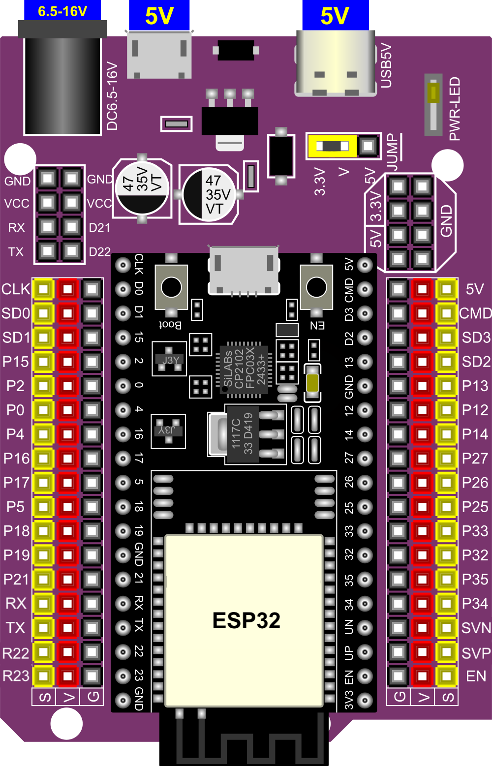
The ESP32 38-pin Expansion Board is a versatile development platform designed by Espressif to simplify prototyping and development with the ESP32 microcontroller. This board features 38 GPIO pins, providing extensive connectivity options for sensors, modules, and peripherals. It is ideal for Internet of Things (IoT) applications, smart devices, and embedded systems.
The expansion board is equipped with a USB-to-serial interface for easy programming and debugging, onboard voltage regulators, and pin headers for seamless integration with breadboards or custom circuits. Its compact design and robust features make it a popular choice for both beginners and experienced developers.
Explore Projects Built with ESP32 38-pin Expansion Board

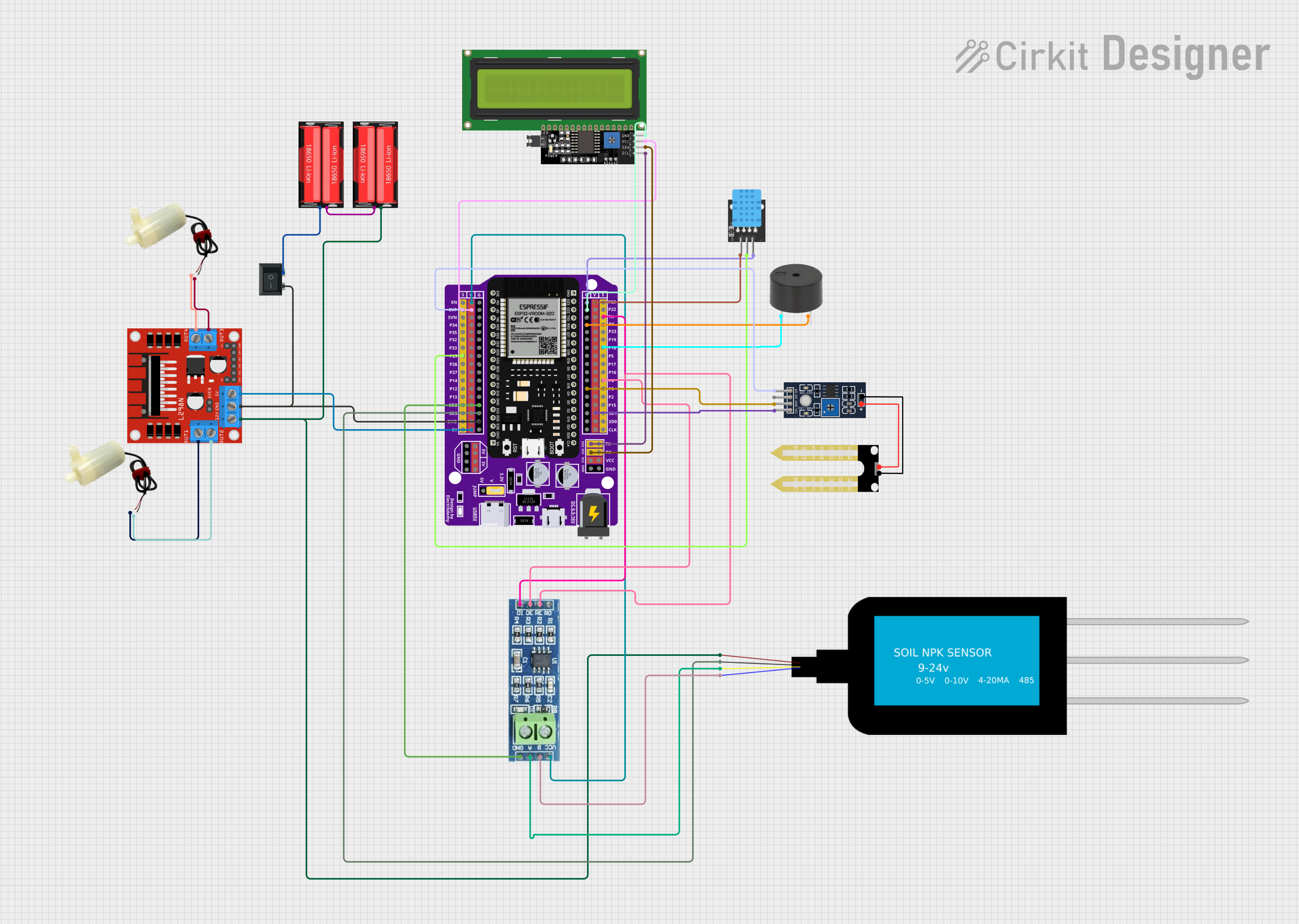
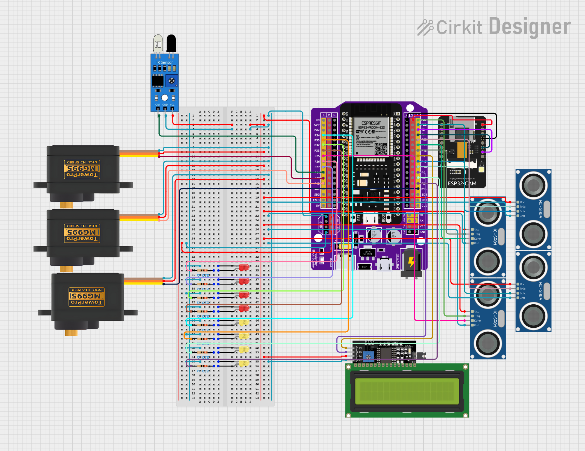

Explore Projects Built with ESP32 38-pin Expansion Board
Common Applications
- IoT devices and smart home automation
- Wearable technology
- Wireless communication (Wi-Fi and Bluetooth)
- Robotics and sensor networks
- Data logging and remote monitoring systems
Technical Specifications
Key Technical Details
| Parameter | Specification |
|---|---|
| Microcontroller | ESP32 (dual-core, 32-bit Xtensa LX6) |
| Operating Voltage | 3.3V |
| Input Voltage (via USB) | 5V |
| GPIO Pins | 38 |
| Wi-Fi Standard | 802.11 b/g/n |
| Bluetooth | v4.2 BR/EDR and BLE |
| Flash Memory | 4MB (varies by model) |
| Clock Speed | Up to 240 MHz |
| USB-to-Serial Chip | CP2102 or CH340 (varies by board) |
| Dimensions | ~57mm x 25mm |
Pin Configuration and Descriptions
The ESP32 38-pin Expansion Board features a total of 38 pins, including GPIO, power, and special-purpose pins. Below is a detailed pinout description:
| Pin Number | Pin Name | Description |
|---|---|---|
| 1 | 3V3 | 3.3V power output |
| 2 | EN | Enable pin (active high, used to reset the chip) |
| 3 | IO1 (TX0) | UART0 Transmit (TX) |
| 4 | IO3 (RX0) | UART0 Receive (RX) |
| 5 | IO4 | General-purpose GPIO pin |
| 6 | IO5 | General-purpose GPIO pin |
| 7 | GND | Ground |
| 8 | IO12 | General-purpose GPIO pin |
| 9 | IO13 | General-purpose GPIO pin |
| 10 | IO14 | General-purpose GPIO pin |
| 11 | IO15 | General-purpose GPIO pin |
| 12 | IO16 | General-purpose GPIO pin |
| 13 | IO17 | General-purpose GPIO pin |
| 14 | IO18 | General-purpose GPIO pin |
| 15 | IO19 | General-purpose GPIO pin |
| 16 | IO21 | General-purpose GPIO pin |
| 17 | IO22 | General-purpose GPIO pin |
| 18 | IO23 | General-purpose GPIO pin |
| 19 | GND | Ground |
| 20 | VIN | Input voltage (5V from USB or external power source) |
| 21 | IO25 | General-purpose GPIO pin |
| 22 | IO26 | General-purpose GPIO pin |
| 23 | IO27 | General-purpose GPIO pin |
| 24 | IO32 | General-purpose GPIO pin |
| 25 | IO33 | General-purpose GPIO pin |
| 26 | IO34 | Input-only GPIO pin |
| 27 | IO35 | Input-only GPIO pin |
| 28 | IO36 (VP) | Input-only GPIO pin (VP, ADC1 channel 0) |
| 29 | IO39 (VN) | Input-only GPIO pin (VN, ADC1 channel 3) |
| 30 | GND | Ground |
Usage Instructions
How to Use the ESP32 38-pin Expansion Board
Powering the Board:
- Connect the board to your computer using a micro-USB cable. The onboard voltage regulator will convert the 5V USB input to 3.3V for the ESP32.
- Alternatively, you can power the board via the VIN pin (5V input) and GND.
Programming the ESP32:
- Install the Arduino IDE and add the ESP32 board support package.
- Go to File > Preferences and add the following URL to the "Additional Board Manager URLs" field:
https://dl.espressif.com/dl/package_esp32_index.json - Open Tools > Board > Boards Manager, search for "ESP32," and install the package.
- Go to File > Preferences and add the following URL to the "Additional Board Manager URLs" field:
- Select the correct board and port in the Arduino IDE:
- Board: "ESP32 Dev Module"
- Port: The COM port assigned to the ESP32.
- Install the Arduino IDE and add the ESP32 board support package.
Connecting Peripherals:
- Use the GPIO pins to connect sensors, actuators, or other modules. Ensure that the voltage levels of connected devices are compatible with the ESP32's 3.3V logic.
Uploading Code:
- Write or load your code in the Arduino IDE.
- Click the Upload button to flash the code to the ESP32. The onboard USB-to-serial chip handles the communication.
Example Code: Blinking an LED
The following example demonstrates how to blink an LED connected to GPIO2:
// Define the GPIO pin for the LED
#define LED_PIN 2

void setup() {
  // Set the LED pin as an output
  pinMode(LED_PIN, OUTPUT);
}

void loop() {
  // Turn the LED on
  digitalWrite(LED_PIN, HIGH);
  delay(1000); // Wait for 1 second

  // Turn the LED off
  digitalWrite(LED_PIN, LOW);
  delay(1000); // Wait for 1 second
}
Important Considerations
- Voltage Levels: The ESP32 operates at 3.3V. Avoid connecting 5V devices directly to its GPIO pins without level shifters.
- Boot Mode: Some GPIO pins (e.g., IO0, IO2, IO15) have specific roles during boot. Avoid pulling these pins high or low unless necessary.
- Power Supply: Ensure a stable power supply, especially when using Wi-Fi or Bluetooth, as these features can cause current spikes.
Troubleshooting and FAQs
Common Issues and Solutions
The board is not detected by the computer:
- Ensure the USB cable is functional and supports data transfer.
- Install the correct USB-to-serial driver (CP2102 or CH340) for your operating system.
Upload fails with a timeout error:
- Press and hold the BOOT button on the board while uploading the code. Release it once the upload starts.
Wi-Fi or Bluetooth is not working:
- Verify that the ESP32 firmware is up to date.
- Check for interference or weak signal strength in your environment.
GPIO pins are not functioning as expected:
- Double-check the pin configuration in your code.
- Ensure that the connected peripherals are compatible with the ESP32's voltage and current ratings.
FAQs
Q: Can I use the ESP32 38-pin Expansion Board with a 5V sensor?
A: Yes, but you will need a level shifter to convert the 5V logic to 3.3V.
Q: How do I reset the ESP32?
A: Press the EN button on the board to reset the microcontroller.
Q: What is the maximum current output of the 3.3V pin?
A: The 3.3V pin can typically supply up to 500mA, depending on the input power source.
Q: Can I use the board with MicroPython?
A: Yes, the ESP32 supports MicroPython. You can flash the MicroPython firmware to the board and use it for development.
This concludes the documentation for the ESP32 38-pin Expansion Board. For further assistance, refer to the official Espressif documentation or community forums.