Cirkit Designer Logo
Cirkit Designer
Your all-in-one circuit design IDE
Home / 
Component Documentation

How to Use Dual 5V Power Supply Mini Board: Examples, Pinouts, and Specs

Image of Dual 5V Power Supply Mini Board
Cirkit Designer LogoDesign with Dual 5V Power Supply Mini Board in Cirkit Designer

Introduction

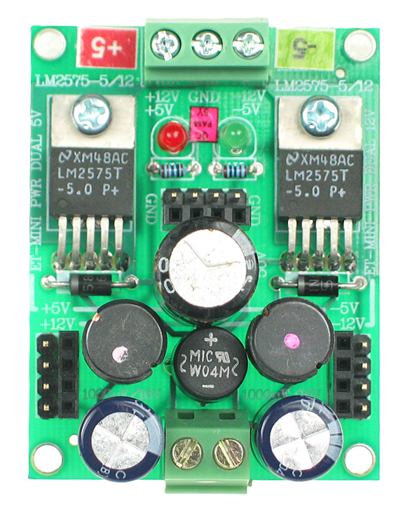
The Dual 5V Power Supply Mini Board is a compact and efficient power supply solution designed to provide two stable 5V outputs. This board is ideal for powering microcontrollers, sensors, and other low-voltage electronic devices. Its small form factor makes it perfect for use in projects where space is limited.

Explore Projects Built with Dual 5V Power Supply Mini Board

Use Cirkit Designer to design, explore, and prototype these projects online. Some projects support real-time simulation. Click "Open Project" to start designing instantly!
Dual 5V Power Supply Distribution Circuit with Toggle Switch Control
Image of rfdriver: A project utilizing Dual 5V Power Supply Mini Board in a practical application
This circuit consists of two 5V 5A power supplies connected to an AC wall plug point, providing DC output through a 12-way connector. The ground connections from both power supplies are interconnected and also connected to the ground pins of two toggle switches. The DC outputs from the power supplies are separately connected to different pins on the 12-way connector, with each power supply output being switchable via one of the toggle switches.
Cirkit Designer LogoOpen Project in Cirkit Designer
12V to 5V Power Supply with LED Indicator and Push Switch
Image of Power Supply LVCO: A project utilizing Dual 5V Power Supply Mini Board in a practical application
This circuit is a 12V to 5V regulated power supply with an LED indicator. It uses a 5408 diode for reverse polarity protection, an LM340T5 7805 voltage regulator to step down the voltage to 5V, and a push switch to control the LED indicator. The circuit also includes capacitors for filtering and a resistor to limit the current through the LED.
Cirkit Designer LogoOpen Project in Cirkit Designer
Battery-Powered Lora G2 Node Station with 18650 Li-ion Batteries and Boost Converter
Image of Custom-Lora-G2-Node: A project utilizing Dual 5V Power Supply Mini Board in a practical application
This circuit is a portable power supply system that uses multiple 18650 Li-ion batteries to provide a stable 5V output through a boost converter. It includes a fast charging module with a USB-C input for recharging the batteries and a battery indicator for monitoring the battery status. The system powers a Lora G2 Node Station, making it suitable for wireless communication applications.
Cirkit Designer LogoOpen Project in Cirkit Designer
Multi-Stage Voltage Regulation and Indicator LED Circuit
Image of Subramanyak_Power_Circuit: A project utilizing Dual 5V Power Supply Mini Board in a practical application
This circuit is designed for power management, featuring buck and boost converters for voltage adjustment, and linear regulators for stable voltage output. It includes LEDs for status indication, and terminal blocks for external connections.
Cirkit Designer LogoOpen Project in Cirkit Designer

Explore Projects Built with Dual 5V Power Supply Mini Board

Use Cirkit Designer to design, explore, and prototype these projects online. Some projects support real-time simulation. Click "Open Project" to start designing instantly!
Image of rfdriver: A project utilizing Dual 5V Power Supply Mini Board in a practical application
Dual 5V Power Supply Distribution Circuit with Toggle Switch Control
This circuit consists of two 5V 5A power supplies connected to an AC wall plug point, providing DC output through a 12-way connector. The ground connections from both power supplies are interconnected and also connected to the ground pins of two toggle switches. The DC outputs from the power supplies are separately connected to different pins on the 12-way connector, with each power supply output being switchable via one of the toggle switches.
Cirkit Designer LogoOpen Project in Cirkit Designer
Image of Power Supply LVCO: A project utilizing Dual 5V Power Supply Mini Board in a practical application
12V to 5V Power Supply with LED Indicator and Push Switch
This circuit is a 12V to 5V regulated power supply with an LED indicator. It uses a 5408 diode for reverse polarity protection, an LM340T5 7805 voltage regulator to step down the voltage to 5V, and a push switch to control the LED indicator. The circuit also includes capacitors for filtering and a resistor to limit the current through the LED.
Cirkit Designer LogoOpen Project in Cirkit Designer
Image of Custom-Lora-G2-Node: A project utilizing Dual 5V Power Supply Mini Board in a practical application
Battery-Powered Lora G2 Node Station with 18650 Li-ion Batteries and Boost Converter
This circuit is a portable power supply system that uses multiple 18650 Li-ion batteries to provide a stable 5V output through a boost converter. It includes a fast charging module with a USB-C input for recharging the batteries and a battery indicator for monitoring the battery status. The system powers a Lora G2 Node Station, making it suitable for wireless communication applications.
Cirkit Designer LogoOpen Project in Cirkit Designer
Image of Subramanyak_Power_Circuit: A project utilizing Dual 5V Power Supply Mini Board in a practical application
Multi-Stage Voltage Regulation and Indicator LED Circuit
This circuit is designed for power management, featuring buck and boost converters for voltage adjustment, and linear regulators for stable voltage output. It includes LEDs for status indication, and terminal blocks for external connections.
Cirkit Designer LogoOpen Project in Cirkit Designer

Common Applications and Use Cases

  • Microcontroller Projects: Powering Arduino, Raspberry Pi, and other microcontroller boards.
  • Sensor Modules: Providing stable power to various sensors and modules.
  • Prototyping: Ideal for breadboard and prototyping applications.
  • Portable Electronics: Suitable for battery-powered projects requiring a stable 5V supply.

Technical Specifications

Key Technical Details

Parameter Value
Input Voltage 6V - 12V DC
Output Voltage 5V DC (x2)
Output Current Up to 1A per output
Power Rating 5W per output
Efficiency Up to 90%
Dimensions 25mm x 25mm x 10mm
Weight 5 grams

Pin Configuration and Descriptions

Pin Number Pin Name Description
1 VIN Input voltage (6V - 12V DC)
2 GND Ground
3 5V OUT1 5V Output 1
4 5V OUT2 5V Output 2

Usage Instructions

How to Use the Component in a Circuit

  1. Connect the Input Voltage:

    • Connect the VIN pin to a DC power source (6V - 12V).
    • Connect the GND pin to the ground of the power source.
  2. Connect the Outputs:

    • Use the 5V OUT1 and 5V OUT2 pins to power your devices.
    • Ensure that the total current drawn from each output does not exceed 1A.

Important Considerations and Best Practices

  • Heat Dissipation: Ensure adequate ventilation around the board to prevent overheating.
  • Input Voltage Range: Do not exceed the specified input voltage range (6V - 12V) to avoid damaging the board.
  • Current Limitation: Do not draw more than 1A from each 5V output to maintain stable operation.
  • Polarity: Double-check the polarity of the input voltage to avoid reverse polarity damage.

Example Usage with Arduino UNO

Here is an example of how to use the Dual 5V Power Supply Mini Board to power an Arduino UNO:

Circuit Diagram

+---------+       +-------------------+
| DC Power|       | Dual 5V Power     |
| Source  |       | Supply Mini Board |
|         |       |                   |
|  +6V    |------>| VIN               |
|  GND    |------>| GND               |
+---------+       |                   |
                  | 5V OUT1 ----------> Arduino 5V Pin
                  | GND     ----------> Arduino GND Pin
                  +-------------------+

Arduino Code Example

// Simple Blink Example
// This code will blink the onboard LED of the Arduino UNO

void setup() {
  pinMode(LED_BUILTIN, OUTPUT); // Set the LED pin as output
}

void loop() {
  digitalWrite(LED_BUILTIN, HIGH); // Turn the LED on
  delay(1000);                     // Wait for 1 second
  digitalWrite(LED_BUILTIN, LOW);  // Turn the LED off
  delay(1000);                     // Wait for 1 second
}

Troubleshooting and FAQs

Common Issues Users Might Face

  1. No Output Voltage:

    • Solution: Check the input voltage and ensure it is within the specified range (6V - 12V). Verify all connections are secure and correct.
  2. Overheating:

    • Solution: Ensure adequate ventilation around the board. Check if the current draw from the outputs exceeds 1A.
  3. Unstable Output Voltage:

    • Solution: Verify that the input voltage is stable and within the specified range. Ensure that the total current draw does not exceed the board's capacity.

FAQs

Q1: Can I use this board to power a Raspberry Pi?

  • A1: Yes, you can use this board to power a Raspberry Pi, but ensure that the total current draw does not exceed 1A per output.

Q2: What happens if I exceed the input voltage range?

  • A2: Exceeding the input voltage range can damage the board and connected devices. Always use a power source within the specified range (6V - 12V).

Q3: Can I use both 5V outputs simultaneously?

  • A3: Yes, you can use both 5V outputs simultaneously, but ensure that the total current draw from each output does not exceed 1A.

Q4: Is there any protection against reverse polarity?

  • A4: No, the board does not have built-in reverse polarity protection. Always double-check the polarity of the input voltage before connecting.

This documentation provides a comprehensive guide to using the Dual 5V Power Supply Mini Board. Whether you are a beginner or an experienced user, following these guidelines will help you effectively integrate this component into your projects.