How to Use ESP32 TYPE C: Examples, Pinouts, and Specs
Introduction
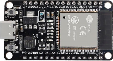
The ESP32 TYPE C is a versatile microcontroller with built-in Wi-Fi and Bluetooth capabilities, designed specifically for Internet of Things (IoT) applications. It features a USB Type-C interface for seamless connectivity and power supply, making it an excellent choice for embedded projects. With its dual-core processor, low power consumption, and extensive GPIO options, the ESP32 TYPE C is ideal for smart home devices, wearable electronics, industrial automation, and more.
Explore Projects Built with ESP32 TYPE C
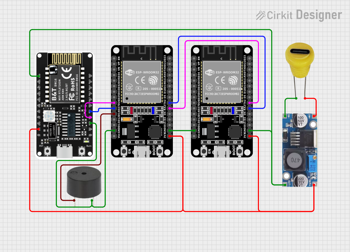
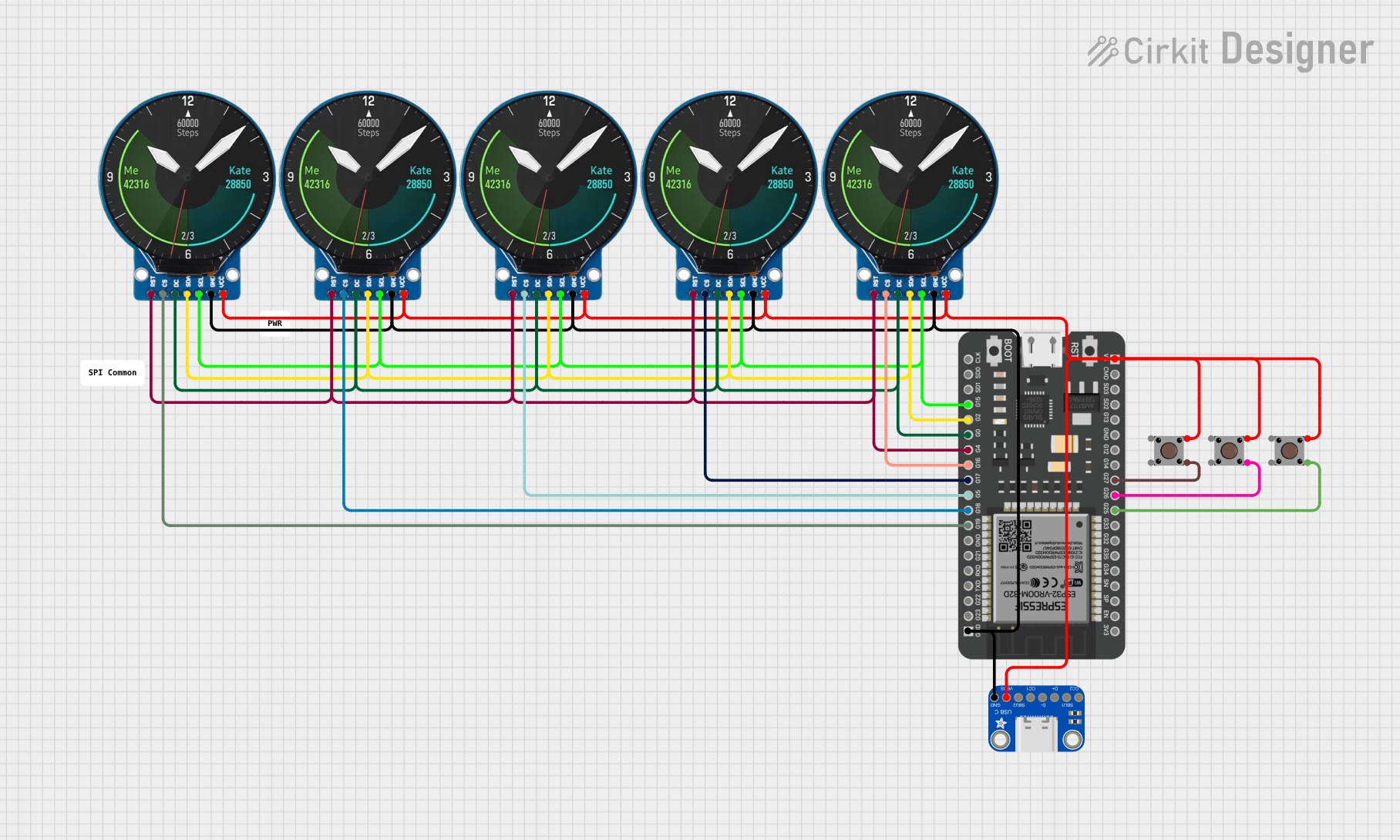


Explore Projects Built with ESP32 TYPE C
Common Applications:
- IoT devices and smart home systems
- Wearable electronics
- Industrial automation and control systems
- Wireless sensor networks
- Robotics and drones
- Prototyping and educational projects
Technical Specifications
Key Technical Details:
| Parameter | Specification |
|---|---|
| Microcontroller | ESP32 dual-core Xtensa LX6 processor |
| Clock Speed | Up to 240 MHz |
| Flash Memory | 4 MB (varies by model) |
| SRAM | 520 KB |
| Wireless Connectivity | Wi-Fi 802.11 b/g/n, Bluetooth 4.2 |
| USB Interface | USB Type-C for power and data |
| Operating Voltage | 3.3V |
| Input Voltage (via USB) | 5V |
| GPIO Pins | 34 |
| ADC Channels | 18 |
| DAC Channels | 2 |
| PWM Channels | 16 |
| Communication Protocols | UART, SPI, I2C, I2S, CAN |
| Power Modes | Active, Sleep, Deep Sleep |
| Operating Temperature | -40°C to 85°C |
Pin Configuration and Descriptions:
| Pin Name | Description |
|---|---|
| VIN | Input power supply (5V via USB Type-C) |
| GND | Ground |
| 3V3 | 3.3V output for external components |
| GPIO0 | General-purpose I/O, boot mode selection |
| GPIO1-34 | General-purpose I/O pins with multiple functions |
| ADC1/ADC2 | Analog-to-digital converter channels |
| DAC1/DAC2 | Digital-to-analog converter channels |
| TXD/RXD | UART transmit/receive pins |
| SCL/SDA | I2C clock and data pins |
| MOSI/MISO | SPI data pins |
| EN | Enable pin to reset the microcontroller |
Usage Instructions
How to Use the ESP32 TYPE C in a Circuit:
Powering the ESP32 TYPE C:
- Connect the USB Type-C port to a 5V power source (e.g., a USB adapter or computer).
- Alternatively, supply 3.3V directly to the 3V3 pin if using an external power source.
Programming the ESP32 TYPE C:
- Install the Arduino IDE and add the ESP32 board package via the Board Manager.
- Select "ESP32 Dev Module" as the board type.
- Connect the ESP32 TYPE C to your computer using a USB Type-C cable.
- Write your code and upload it to the board.
Connecting Peripherals:
- Use the GPIO pins to connect sensors, actuators, or other peripherals.
- Ensure that the voltage levels of connected devices are compatible with the ESP32's 3.3V logic.
Wi-Fi and Bluetooth Setup:
- Use the built-in libraries (
WiFi.handBluetoothSerial.h) to configure wireless communication.
- Use the built-in libraries (
Example Code for Arduino IDE:
The following example demonstrates how to connect the ESP32 TYPE C to a Wi-Fi network and blink an LED:
#include <WiFi.h> // Include the Wi-Fi library

// Replace with your network credentials
const char* ssid = "Your_SSID";
const char* password = "Your_PASSWORD";

const int ledPin = 2; // GPIO2 is typically connected to an onboard LED

void setup() {
  pinMode(ledPin, OUTPUT); // Set the LED pin as an output
  Serial.begin(115200);    // Initialize serial communication

  // Connect to Wi-Fi
  Serial.print("Connecting to Wi-Fi");
  WiFi.begin(ssid, password);
  while (WiFi.status() != WL_CONNECTED) {
    delay(500);
    Serial.print(".");
  }
  Serial.println("\nWi-Fi connected!");
  Serial.print("IP Address: ");
  Serial.println(WiFi.localIP()); // Print the device's IP address
}

void loop() {
  digitalWrite(ledPin, HIGH); // Turn the LED on
  delay(1000);               // Wait for 1 second
  digitalWrite(ledPin, LOW);  // Turn the LED off
  delay(1000);               // Wait for 1 second
}
Important Considerations:
- Voltage Levels: Ensure that all connected peripherals operate at 3.3V logic levels to avoid damaging the ESP32.
- Power Supply: Use a stable 5V power source when powering the ESP32 via USB.
- Boot Mode: To enter bootloader mode, hold down the BOOT button while pressing the EN (reset) button.
- Heat Management: If running intensive tasks, consider adding a heatsink to manage heat dissipation.
Troubleshooting and FAQs
Common Issues:
ESP32 Not Detected by Computer:
- Ensure the USB Type-C cable supports data transfer (not just charging).
- Install the correct USB-to-serial driver for your operating system.
Wi-Fi Connection Fails:
- Double-check the SSID and password in your code.
- Ensure the Wi-Fi network is within range and not using unsupported security protocols.
Code Upload Fails:
- Verify that the correct board and COM port are selected in the Arduino IDE.
- Hold the BOOT button while uploading the code to force the ESP32 into bootloader mode.
GPIO Pin Issues:
- Some GPIO pins have specific functions during boot (e.g., GPIO0 for boot mode).
- Avoid using these pins for general I/O unless necessary.
Tips for Troubleshooting:
- Use the Serial Monitor in the Arduino IDE to debug your code and monitor output.
- Check for loose connections or faulty components in your circuit.
- Refer to the ESP32 datasheet for detailed information on pin functions and electrical characteristics.
FAQs:
Q: Can I power the ESP32 TYPE C with a battery?
A: Yes, you can use a 3.7V LiPo battery with a voltage regulator to supply 3.3V to the 3V3 pin.
Q: Does the ESP32 TYPE C support OTA updates?
A: Yes, the ESP32 supports Over-The-Air (OTA) updates, allowing you to upload code wirelessly.
Q: Can I use the ESP32 TYPE C with MicroPython?
A: Yes, the ESP32 is compatible with MicroPython. You can flash the MicroPython firmware to the board and program it using Python.
Q: What is the maximum range of the ESP32's Wi-Fi?
A: The Wi-Fi range depends on environmental factors but typically extends up to 100 meters in open spaces.
Q: How do I reset the ESP32 TYPE C?
A: Press the EN (reset) button to restart the microcontroller.