Cirkit Designer Logo
Cirkit Designer
Your all-in-one circuit design IDE
Home / 
Component Documentation

How to Use EC200U 4G LTE GNSS Industrial Modem: Examples, Pinouts, and Specs

Image of EC200U 4G LTE GNSS Industrial Modem
Cirkit Designer LogoDesign with EC200U 4G LTE GNSS Industrial Modem in Cirkit Designer

Introduction

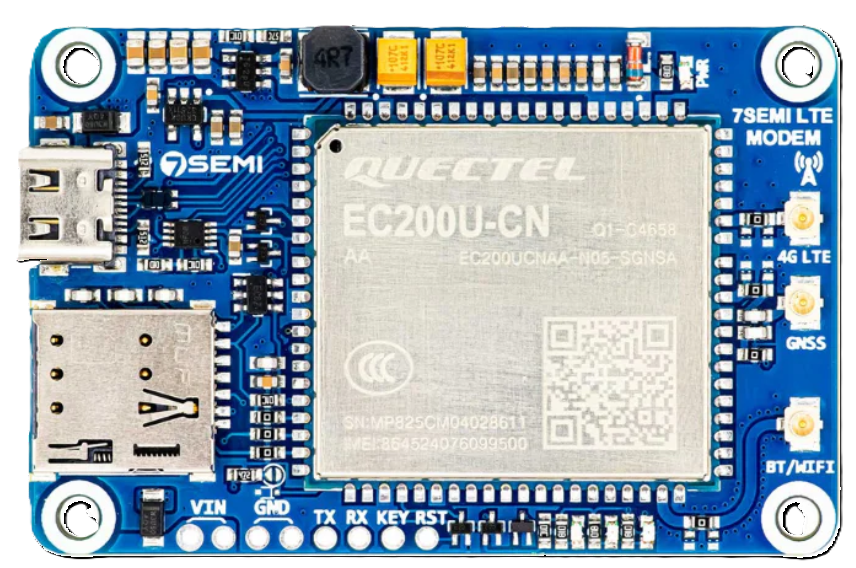
The EC200U is a compact industrial modem manufactured by 7Semi (Part ID: TIFCC0227) that combines 4G LTE connectivity with GNSS (Global Navigation Satellite System) capabilities. Designed for IoT applications, this modem ensures reliable data transmission and precise location tracking, even in harsh environments. Its robust design and versatile features make it ideal for industrial automation, fleet management, smart agriculture, and remote monitoring systems.

Explore Projects Built with EC200U 4G LTE GNSS Industrial Modem

Use Cirkit Designer to design, explore, and prototype these projects online. Some projects support real-time simulation. Click "Open Project" to start designing instantly!
Satellite Compass and Network-Integrated GPS Data Processing System
Image of GPS 시스템 측정 구성도_241016: A project utilizing EC200U 4G LTE GNSS Industrial Modem in a practical application
This circuit comprises a satellite compass, a mini PC, two GPS antennas, power supplies, a network switch, media converters, and an atomic rubidium clock. The satellite compass is powered by a triple output DC power supply and interfaces with an RS232 splitter for 1PPS signals. The mini PCs are connected to the USRP B200 devices via USB for data and power, and to media converters via Ethernet, which in turn connect to a network switch using fiber optic links. The antennas are connected to the USRP B200s through RF directional couplers, and the atomic clock provides a 1PPS input to the RS232 splitter.
Cirkit Designer LogoOpen Project in Cirkit Designer
Satellite-Based Timing and Navigation System with SDR and Atomic Clock Synchronization
Image of GPS 시스템 측정 구성도_Confirm: A project utilizing EC200U 4G LTE GNSS Industrial Modem in a practical application
This circuit appears to be a complex system involving power supply management, GPS and timing synchronization, and data communication. It includes a SI-TEX G1 Satellite Compass for GPS data, an XHTF1021 Atomic Rubidium Clock for precise timing, and Ettus USRP B200 units for software-defined radio communication. Power is supplied through various SMPS units and distributed via terminal blocks and DC jacks. Data communication is facilitated by Beelink MINI S12 N95 computers, RS232 splitters, and a 1000BASE-T Media Converter for network connectivity. RF Directional Couplers are used to interface antennas with the USRP units, and the entire system is likely contained within cases for protection and organization.
Cirkit Designer LogoOpen Project in Cirkit Designer
ESP8266 NodeMCU with LoRa and RS-485 Communication and Ethernet Connectivity
Image of Wiring Diagram LoRa: A project utilizing EC200U 4G LTE GNSS Industrial Modem in a practical application
This circuit serves as a multi-protocol communication hub featuring two ESP8266 NodeMCUs for processing, each connected to a LoRa Ra-02 SX1278 for long-range wireless communication. One NodeMCU is also connected to an RS-485 module for serial communication and a W5500 Ethernet module for network connectivity, with MB102 modules supplying power.
Cirkit Designer LogoOpen Project in Cirkit Designer
Cellular-Enabled IoT Device with Real-Time Clock and Power Management
Image of LRCM PHASE 2 BASIC: A project utilizing EC200U 4G LTE GNSS Industrial Modem in a practical application
This circuit features a LilyGo-SIM7000G module for cellular communication and GPS functionality, interfaced with an RTC DS3231 for real-time clock capabilities. It includes voltage sensing through two voltage sensor modules, and uses an 8-channel opto-coupler for isolating different parts of the circuit. Power management is handled by a buck converter connected to a DC power source and batteries, with a fuse for protection and a rocker switch for on/off control. Additionally, there's an LED for indication purposes.
Cirkit Designer LogoOpen Project in Cirkit Designer

Explore Projects Built with EC200U 4G LTE GNSS Industrial Modem

Use Cirkit Designer to design, explore, and prototype these projects online. Some projects support real-time simulation. Click "Open Project" to start designing instantly!
Image of GPS 시스템 측정 구성도_241016: A project utilizing EC200U 4G LTE GNSS Industrial Modem in a practical application
Satellite Compass and Network-Integrated GPS Data Processing System
This circuit comprises a satellite compass, a mini PC, two GPS antennas, power supplies, a network switch, media converters, and an atomic rubidium clock. The satellite compass is powered by a triple output DC power supply and interfaces with an RS232 splitter for 1PPS signals. The mini PCs are connected to the USRP B200 devices via USB for data and power, and to media converters via Ethernet, which in turn connect to a network switch using fiber optic links. The antennas are connected to the USRP B200s through RF directional couplers, and the atomic clock provides a 1PPS input to the RS232 splitter.
Cirkit Designer LogoOpen Project in Cirkit Designer
Image of GPS 시스템 측정 구성도_Confirm: A project utilizing EC200U 4G LTE GNSS Industrial Modem in a practical application
Satellite-Based Timing and Navigation System with SDR and Atomic Clock Synchronization
This circuit appears to be a complex system involving power supply management, GPS and timing synchronization, and data communication. It includes a SI-TEX G1 Satellite Compass for GPS data, an XHTF1021 Atomic Rubidium Clock for precise timing, and Ettus USRP B200 units for software-defined radio communication. Power is supplied through various SMPS units and distributed via terminal blocks and DC jacks. Data communication is facilitated by Beelink MINI S12 N95 computers, RS232 splitters, and a 1000BASE-T Media Converter for network connectivity. RF Directional Couplers are used to interface antennas with the USRP units, and the entire system is likely contained within cases for protection and organization.
Cirkit Designer LogoOpen Project in Cirkit Designer
Image of Wiring Diagram LoRa: A project utilizing EC200U 4G LTE GNSS Industrial Modem in a practical application
ESP8266 NodeMCU with LoRa and RS-485 Communication and Ethernet Connectivity
This circuit serves as a multi-protocol communication hub featuring two ESP8266 NodeMCUs for processing, each connected to a LoRa Ra-02 SX1278 for long-range wireless communication. One NodeMCU is also connected to an RS-485 module for serial communication and a W5500 Ethernet module for network connectivity, with MB102 modules supplying power.
Cirkit Designer LogoOpen Project in Cirkit Designer
Image of LRCM PHASE 2 BASIC: A project utilizing EC200U 4G LTE GNSS Industrial Modem in a practical application
Cellular-Enabled IoT Device with Real-Time Clock and Power Management
This circuit features a LilyGo-SIM7000G module for cellular communication and GPS functionality, interfaced with an RTC DS3231 for real-time clock capabilities. It includes voltage sensing through two voltage sensor modules, and uses an 8-channel opto-coupler for isolating different parts of the circuit. Power management is handled by a buck converter connected to a DC power source and batteries, with a fuse for protection and a rocker switch for on/off control. Additionally, there's an LED for indication purposes.
Cirkit Designer LogoOpen Project in Cirkit Designer

Common Applications

  • Industrial IoT: Real-time data transmission for sensors and devices in factories.
  • Fleet Management: Vehicle tracking and telematics for logistics and transportation.
  • Smart Agriculture: Remote monitoring of environmental conditions and equipment.
  • Remote Monitoring: Data collection and control in off-grid or hard-to-reach locations.

Technical Specifications

Key Technical Details

Parameter Specification
Manufacturer 7Semi
Part ID TIFCC0227
Cellular Connectivity 4G LTE (Cat 4)
GNSS Support GPS, GLONASS, BeiDou, Galileo
Operating Voltage 3.3V to 4.3V
Power Consumption Idle: ~15mA, Active: ~500mA (peak during transmission)
Operating Temperature -40°C to +85°C
Data Rate Up to 150 Mbps (downlink), 50 Mbps (uplink)
Interface UART, USB 2.0, GPIO
Antenna Interfaces 1x LTE antenna port, 1x GNSS antenna port
Dimensions 30mm x 30mm x 2.8mm
Certifications CE, FCC, RoHS

Pin Configuration and Descriptions

Pin Number Pin Name Description
1 VCC Power supply input (3.3V to 4.3V).
2 GND Ground connection.
3 TXD UART Transmit Data (connect to RXD of host).
4 RXD UART Receive Data (connect to TXD of host).
5 USB_D+ USB 2.0 Data Positive.
6 USB_D- USB 2.0 Data Negative.
7 GNSS_TX GNSS UART Transmit Data.
8 GNSS_RX GNSS UART Receive Data.
9 RESET Active-low reset pin.
10 PWR_KEY Power-on key (active low, hold for 1 second to power on/off).
11 GPIO1 General-purpose input/output pin.
12 GPIO2 General-purpose input/output pin.

Usage Instructions

How to Use the EC200U in a Circuit

  1. Power Supply: Connect the VCC pin to a regulated 3.3V-4.3V power source and the GND pin to ground.
  2. UART Communication: Connect the TXD and RXD pins to the corresponding RXD and TXD pins of your microcontroller or host device.
  3. USB Interface: For USB communication, connect the USB_D+ and USB_D- pins to the USB data lines of your host device.
  4. GNSS Antenna: Attach a compatible GNSS antenna to the GNSS antenna port for location tracking.
  5. LTE Antenna: Connect an LTE antenna to the LTE antenna port for cellular connectivity.
  6. Power On: Pull the PWR_KEY pin low for at least 1 second to power on the modem.

Important Considerations

  • Antenna Placement: Ensure that the LTE and GNSS antennas are placed in locations with minimal interference for optimal performance.
  • Power Supply: Use a stable power source capable of handling peak current demands (~500mA).
  • Heat Dissipation: If operating in high-temperature environments, ensure proper ventilation or heat sinking to prevent overheating.
  • Firmware Updates: Periodically check for firmware updates from 7Semi to ensure compatibility and performance.

Example: Connecting EC200U to Arduino UNO

Below is an example of how to interface the EC200U with an Arduino UNO for basic UART communication.

Circuit Connections

EC200U Pin Arduino UNO Pin
VCC 3.3V
GND GND
TXD Pin 10 (RX)
RXD Pin 11 (TX)
PWR_KEY Digital Pin 9

Arduino Code Example

#include <SoftwareSerial.h>

// Define software serial pins for EC200U communication
SoftwareSerial ec200uSerial(10, 11); // RX = Pin 10, TX = Pin 11

#define PWR_KEY 9 // Power key pin

void setup() {
  // Initialize serial communication
  Serial.begin(9600); // For debugging via Serial Monitor
  ec200uSerial.begin(9600); // Communication with EC200U

  // Configure PWR_KEY pin
  pinMode(PWR_KEY, OUTPUT);
  digitalWrite(PWR_KEY, HIGH); // Set PWR_KEY high initially

  // Power on the EC200U
  Serial.println("Powering on EC200U...");
  digitalWrite(PWR_KEY, LOW); // Pull PWR_KEY low
  delay(1000); // Hold for 1 second
  digitalWrite(PWR_KEY, HIGH); // Release PWR_KEY
  delay(5000); // Wait for the modem to initialize
  Serial.println("EC200U powered on.");
}

void loop() {
  // Send AT command to EC200U
  ec200uSerial.println("AT");
  delay(1000); // Wait for response

  // Read and print response from EC200U
  while (ec200uSerial.available()) {
    char c = ec200uSerial.read();
    Serial.print(c); // Print response to Serial Monitor
  }
}

Troubleshooting and FAQs

Common Issues and Solutions

  1. Modem Not Powering On

    • Ensure the PWR_KEY pin is held low for at least 1 second during power-on.
    • Verify that the power supply provides sufficient current (500mA peak).
  2. No Response to AT Commands

    • Check the UART connections (TXD and RXD) between the modem and the host device.
    • Ensure the baud rate matches (default: 9600 bps).
    • Confirm that the modem is powered on (check the status LED, if available).
  3. Poor GNSS Signal

    • Verify that the GNSS antenna is connected and placed in an open area with a clear view of the sky.
    • Avoid placing the antenna near sources of RF interference.
  4. LTE Connectivity Issues

    • Ensure the LTE antenna is securely connected and positioned for optimal signal reception.
    • Check the SIM card for proper insertion and activation.

FAQs

  • Q: Can the EC200U operate on 2G or 3G networks?
    A: No, the EC200U is designed specifically for 4G LTE networks.

  • Q: What is the maximum cable length for the antennas?
    A: It is recommended to use cables shorter than 3 meters to minimize signal loss.

  • Q: Does the modem support SMS functionality?
    A: Yes, the EC200U supports SMS sending and receiving via AT commands.

  • Q: Can I use the EC200U with a Raspberry Pi?
    A: Yes, the EC200U can be connected to a Raspberry Pi via UART or USB.


This concludes the documentation for the EC200U 4G LTE GNSS Industrial Modem. For further assistance, refer to the official datasheet or contact 7Semi support.