How to Use sn75173N: Examples, Pinouts, and Specs
Introduction
The SN75173N, manufactured by Texas Instruments (TI), is a quad differential line driver designed for high-speed data transmission. It is widely used in RS-485 and RS-422 communication systems, offering robust and reliable data transfer over long distances. The component is engineered to provide excellent noise immunity, making it ideal for industrial, automotive, and telecommunications applications.
Explore Projects Built with sn75173N


Explore Projects Built with sn75173N
Common Applications and Use Cases
- RS-485 and RS-422 communication networks
- Industrial automation and control systems
- Long-distance data transmission
- Motor control and robotics
- Telecommunications equipment
Technical Specifications
Key Technical Details
- Supply Voltage (Vcc): 4.75V to 5.25V
- Input Voltage Range: -0.5V to Vcc + 0.5V
- Output Voltage Range: -0.5V to 6V
- Differential Output Voltage: ±6V (maximum)
- Data Rate: Up to 10 Mbps
- Operating Temperature Range: 0°C to 70°C
- Power Dissipation: 1W (maximum)
- Package Type: 16-pin DIP (Dual Inline Package)
Pin Configuration and Descriptions
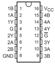
The SN75173N is a 16-pin IC. Below is the pinout and description:
| Pin Number | Pin Name | Description |
|---|---|---|
| 1 | 1A | Input for Driver 1 |
| 2 | 1Y | Non-inverting Output for Driver 1 |
| 3 | 1Z | Inverting Output for Driver 1 |
| 4 | GND | Ground |
| 5 | 2A | Input for Driver 2 |
| 6 | 2Y | Non-inverting Output for Driver 2 |
| 7 | 2Z | Inverting Output for Driver 2 |
| 8 | ENABLE | Enable Pin for All Drivers (Active High) |
| 9 | 3A | Input for Driver 3 |
| 10 | 3Y | Non-inverting Output for Driver 3 |
| 11 | 3Z | Inverting Output for Driver 3 |
| 12 | Vcc | Positive Supply Voltage |
| 13 | 4A | Input for Driver 4 |
| 14 | 4Y | Non-inverting Output for Driver 4 |
| 15 | 4Z | Inverting Output for Driver 4 |
| 16 | ENABLE | Enable Pin for All Drivers (Active High, duplicate of Pin 8 for redundancy) |
Usage Instructions
How to Use the SN75173N in a Circuit
Power Supply:
- Connect the Vcc pin (Pin 12) to a regulated 5V power supply.
- Connect the GND pin (Pin 4) to the ground of the circuit.
Input Signals:
- Provide the input signals to the
Apins (1A, 2A, 3A, 4A). - Ensure the input voltage levels are within the specified range (-0.5V to Vcc + 0.5V).
- Provide the input signals to the
Enable Pin:
- The ENABLE pin (Pins 8 and 16) must be set HIGH to activate the drivers.
- If the ENABLE pin is LOW, all outputs will be in a high-impedance state.
Output Connections:
- Connect the differential outputs (
YandZpins) to the corresponding RS-485 or RS-422 bus lines. - Use proper termination resistors at the ends of the bus to minimize signal reflections.
- Connect the differential outputs (
Termination Resistors:
- For RS-485 applications, use a 120-ohm resistor between the
YandZlines at each end of the bus.
- For RS-485 applications, use a 120-ohm resistor between the
Important Considerations and Best Practices
- Avoid exceeding the maximum voltage ratings to prevent damage to the IC.
- Use decoupling capacitors (e.g., 0.1 µF) near the Vcc pin to filter noise from the power supply.
- Ensure proper grounding to minimize noise and improve signal integrity.
- For long-distance communication, use twisted-pair cables to reduce electromagnetic interference (EMI).
Example: Connecting SN75173N to an Arduino UNO
The SN75173N can be used with an Arduino UNO to drive an RS-485 communication bus. Below is an example circuit and code:
Circuit Connections
- Connect the Arduino's digital pins to the
Ainputs of the SN75173N (e.g., Pin 2 to 1A, Pin 3 to 2A). - Connect the ENABLE pin to a digital pin on the Arduino (e.g., Pin 4).
- Connect the
YandZoutputs to the RS-485 bus lines. - Power the SN75173N with a 5V supply and connect the GND pin to the Arduino's ground.
Arduino Code
// Example code to control the SN75173N with an Arduino UNO
const int enablePin = 4;  // Pin to control the ENABLE pin
const int driver1A = 2;   // Pin connected to 1A input
const int driver2A = 3;   // Pin connected to 2A input

void setup() {
  pinMode(enablePin, OUTPUT);  // Set ENABLE pin as output
  pinMode(driver1A, OUTPUT);   // Set Driver 1A as output
  pinMode(driver2A, OUTPUT);   // Set Driver 2A as output

  digitalWrite(enablePin, HIGH);  // Enable the SN75173N
}

void loop() {
  // Send a HIGH signal on Driver 1A
  digitalWrite(driver1A, HIGH);
  delay(1000);  // Wait for 1 second

  // Send a LOW signal on Driver 1A
  digitalWrite(driver1A, LOW);
  delay(1000);  // Wait for 1 second

  // Toggle Driver 2A
  digitalWrite(driver2A, HIGH);
  delay(500);  // Wait for 0.5 seconds
  digitalWrite(driver2A, LOW);
  delay(500);  // Wait for 0.5 seconds
}
Troubleshooting and FAQs
Common Issues and Solutions
No Output Signal:
- Ensure the ENABLE pin is set HIGH.
- Verify that the input signals are within the specified voltage range.
- Check the power supply connections and ensure Vcc is 5V.
Distorted Output Signal:
- Verify the termination resistors on the RS-485 bus.
- Use twisted-pair cables for the differential lines to reduce noise.
- Check for proper grounding in the circuit.
Overheating of the IC:
- Ensure the output load does not exceed the maximum current rating.
- Verify that the supply voltage is within the specified range.
High-Impedance Outputs:
- Check if the ENABLE pin is LOW. Set it HIGH to activate the drivers.
FAQs
Q: Can the SN75173N be used for single-ended communication?
A: No, the SN75173N is designed for differential communication (e.g., RS-485, RS-422). For single-ended communication, consider using a standard line driver.
Q: What is the maximum cable length supported by the SN75173N?
A: The maximum cable length depends on the data rate and cable type. For RS-485, it typically supports up to 1200 meters at lower data rates.
Q: Can I use the SN75173N with a 3.3V microcontroller?
A: The SN75173N requires a 5V supply for proper operation. Use level shifters to interface with 3.3V logic.
Q: Is the SN75173N suitable for multi-drop communication?
A: Yes, the SN75173N supports multi-drop communication in RS-485 networks. Ensure proper termination and biasing resistors are used.