How to Use CCTV 36 IR LED board : Examples, Pinouts, and Specs
Introduction
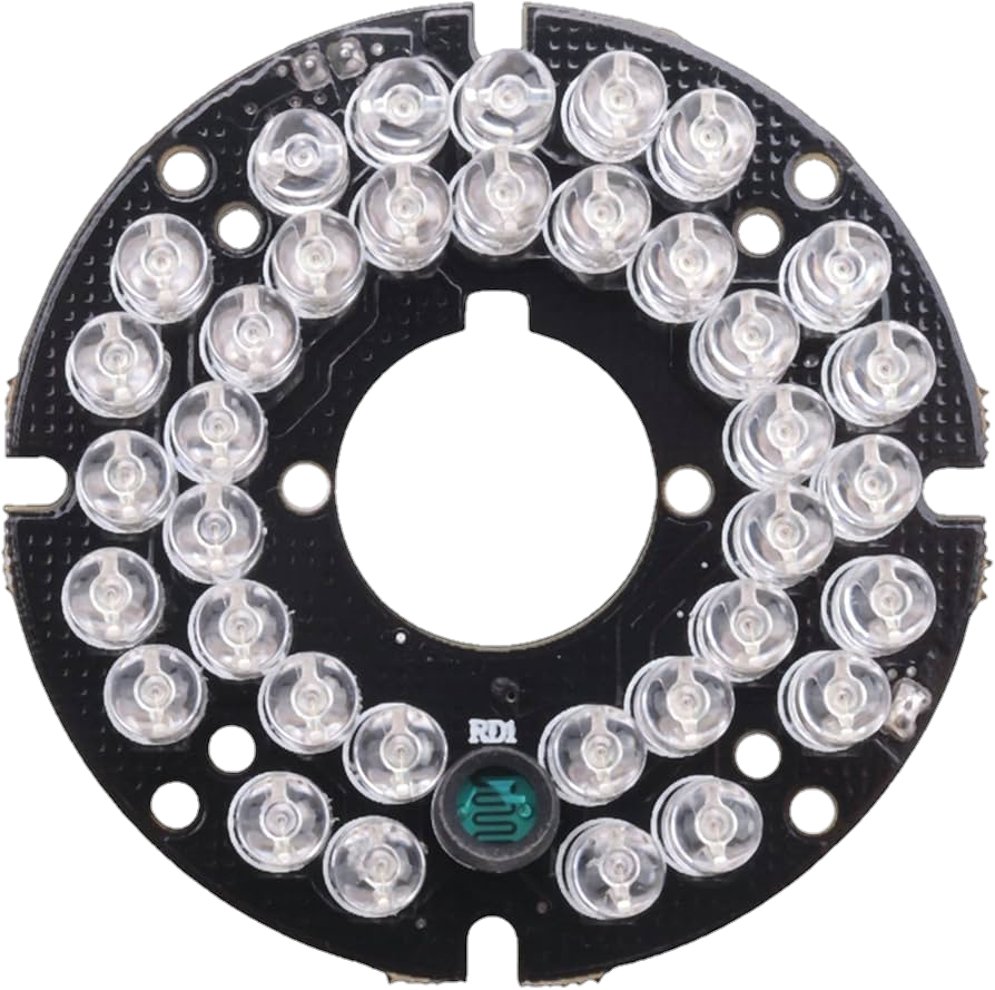
The CCTV 36 IR LED Board (Manufacturer: Laetitia, Part ID: 67) is a specialized circuit board equipped with 36 infrared (IR) LEDs. It is designed to provide illumination in low-light or complete darkness, making it an essential component for night vision in CCTV cameras. The IR LEDs emit light in the infrared spectrum, which is invisible to the human eye but can be captured by camera sensors, enabling clear video footage in dark environments.
Explore Projects Built with CCTV 36 IR LED board
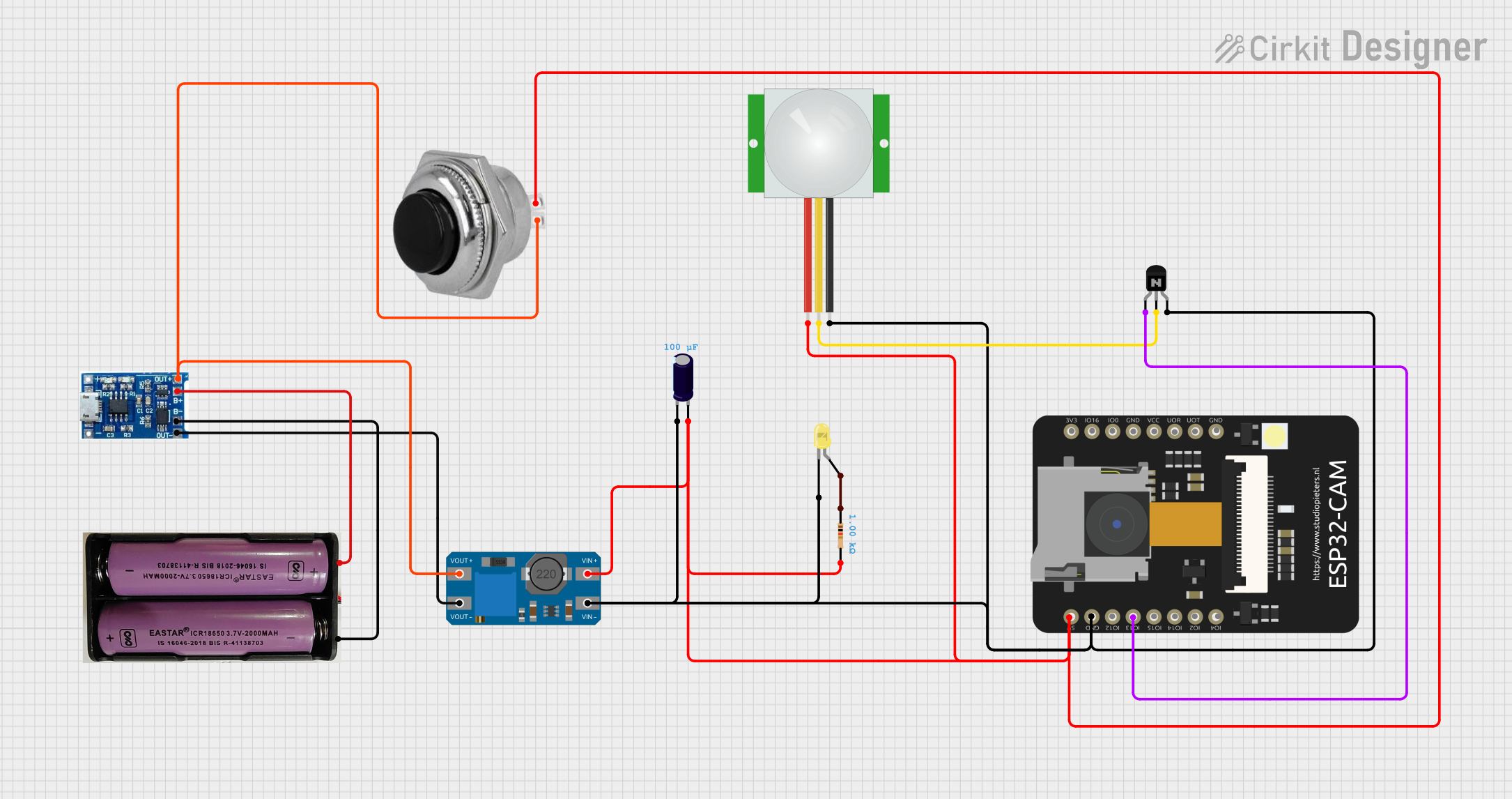


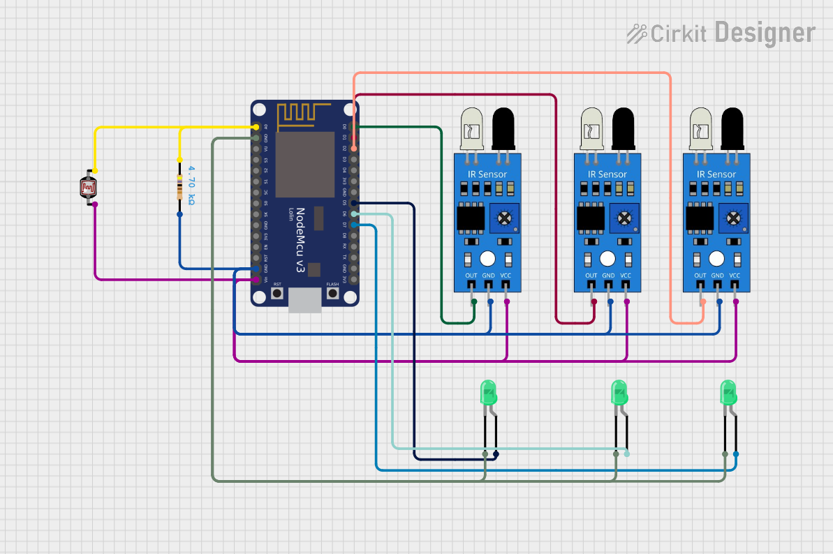
Explore Projects Built with CCTV 36 IR LED board
Common Applications and Use Cases
- Night vision for CCTV security cameras
- Wildlife monitoring and photography
- Industrial and warehouse surveillance
- Home security systems
- Robotics and automation requiring IR illumination
Technical Specifications
Key Technical Details
| Parameter | Value |
|---|---|
| Manufacturer | Laetitia |
| Part ID | 67 |
| Number of LEDs | 36 |
| LED Type | Infrared (IR) |
| Wavelength | 850 nm (typical) |
| Operating Voltage | 12V DC |
| Current Consumption | ~300 mA |
| Illumination Range | Up to 20 meters |
| Board Dimensions | 50 mm (diameter, circular) |
| Mounting Holes | 4 holes (for easy installation) |
Pin Configuration and Descriptions
The CCTV 36 IR LED Board typically has two pins for power input. Below is the pin configuration:
| Pin Number | Label | Description |
|---|---|---|
| 1 | VCC | Positive power supply (12V DC) |
| 2 | GND | Ground connection |
Usage Instructions
How to Use the Component in a Circuit
- Power Supply: Connect the board to a stable 12V DC power supply. Ensure the power source can provide at least 300 mA of current to avoid underpowering the LEDs.
- Polarity: Double-check the polarity of the connections:
- Connect the VCC pin to the positive terminal of the power supply.
- Connect the GND pin to the negative terminal of the power supply.
- Mounting: Use the provided mounting holes to securely attach the board to the desired location. Ensure the IR LEDs face the area to be illuminated.
- Integration with CCTV Camera: Position the board around the camera lens or in close proximity to ensure the IR illumination aligns with the camera's field of view.
Important Considerations and Best Practices
- Heat Dissipation: The IR LEDs may generate heat during prolonged use. Ensure proper ventilation or heat sinking to prevent overheating.
- Power Supply Quality: Use a regulated 12V DC power supply to avoid voltage fluctuations that could damage the LEDs.
- Distance and Angle: For optimal performance, position the board within 20 meters of the target area. Adjust the angle to maximize illumination coverage.
- Camera Compatibility: Verify that the CCTV camera is sensitive to 850 nm IR light, as some cameras may not support this wavelength.
Arduino Integration Example
While the CCTV 36 IR LED Board is not directly controlled by an Arduino, you can use a relay module to switch the board on or off based on environmental conditions (e.g., low light detected by a photoresistor). Below is an example:
// Example: Controlling the IR LED board with an Arduino and a relay module
// The relay is connected to pin 7, and a photoresistor is used to detect light levels.

const int relayPin = 7;       // Pin connected to the relay module
const int photoResistorPin = A0; // Analog pin for the photoresistor
const int threshold = 500;    // Light level threshold for turning on the IR LEDs

void setup() {
  pinMode(relayPin, OUTPUT);  // Set relay pin as output
  digitalWrite(relayPin, LOW); // Ensure relay is off initially
  Serial.begin(9600);         // Initialize serial communication
}

void loop() {
  int lightLevel = analogRead(photoResistorPin); // Read light level
  Serial.println(lightLevel); // Print light level for debugging

  if (lightLevel < threshold) {
    // If light level is below threshold, turn on the IR LED board
    digitalWrite(relayPin, HIGH);
  } else {
    // Otherwise, turn off the IR LED board
    digitalWrite(relayPin, LOW);
  }

  delay(500); // Small delay for stability
}
Notes:
- Replace the photoresistor and threshold values with appropriate components and calibration for your setup.
- Ensure the relay module can handle the current and voltage requirements of the IR LED board.
Troubleshooting and FAQs
Common Issues and Solutions
IR LEDs Not Turning On
- Cause: Incorrect power supply or polarity.
- Solution: Verify the power supply voltage (12V DC) and ensure correct polarity (VCC to positive, GND to negative).
Overheating
- Cause: Prolonged use without proper ventilation.
- Solution: Add a heat sink or improve airflow around the board.
Insufficient Illumination
- Cause: Board positioned too far from the target area.
- Solution: Reposition the board within the recommended 20-meter range.
Interference with Camera
- Cause: Misalignment of the IR LEDs with the camera's field of view.
- Solution: Adjust the board's position and angle to align with the camera.
FAQs
Q1: Can I use a power supply higher than 12V?
A1: No, using a higher voltage can damage the IR LEDs. Always use a regulated 12V DC power supply.
Q2: How do I know if the IR LEDs are working?
A2: IR light is invisible to the human eye, but you can use a smartphone camera to check. Point the camera at the LEDs, and you should see a faint red glow.
Q3: Can I dim the IR LEDs?
A3: The board is not designed for dimming. If dimming is required, consider using a PWM-controlled circuit with compatible components.
Q4: Is the board weatherproof?
A4: No, the board is not weatherproof. For outdoor use, enclose it in a weatherproof housing.
By following this documentation, you can effectively integrate and troubleshoot the Laetitia CCTV 36 IR LED Board (Part ID: 67) in your projects.