How to Use NPN Transistor (EBC): Examples, Pinouts, and Specs
Introduction
An NPN transistor is a fundamental electronic component used in various applications to amplify or switch electronic signals. It is a type of bipolar junction transistor (BJT) consisting of three layers of semiconductor material. In the EBC (Emitter-Base-Collector) configuration, the transistor has its emitter (E), base (B), and collector (C) terminals arranged in a specific order. This configuration is widely used in electronic circuits for controlling current flow and can be found in applications such as amplifiers, switches, and digital logic circuits.
Explore Projects Built with NPN Transistor (EBC)
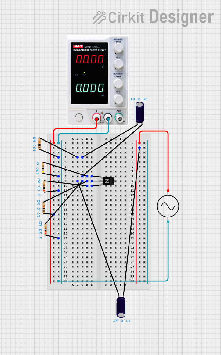
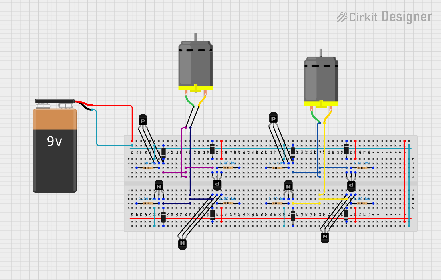
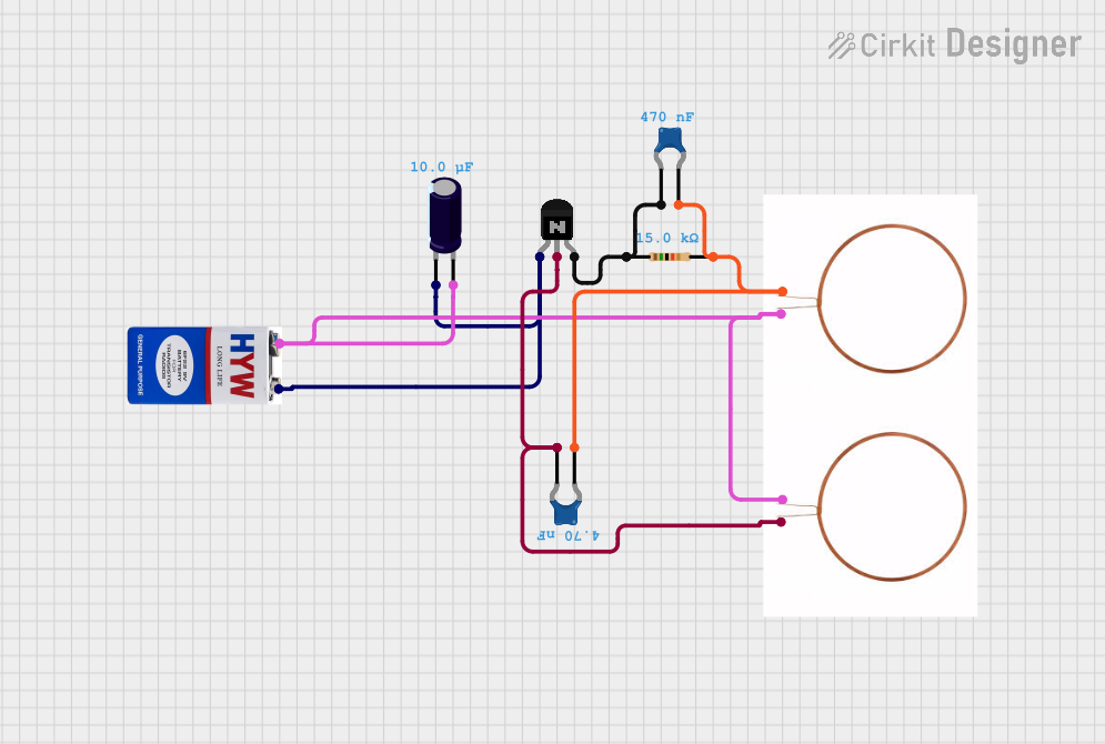
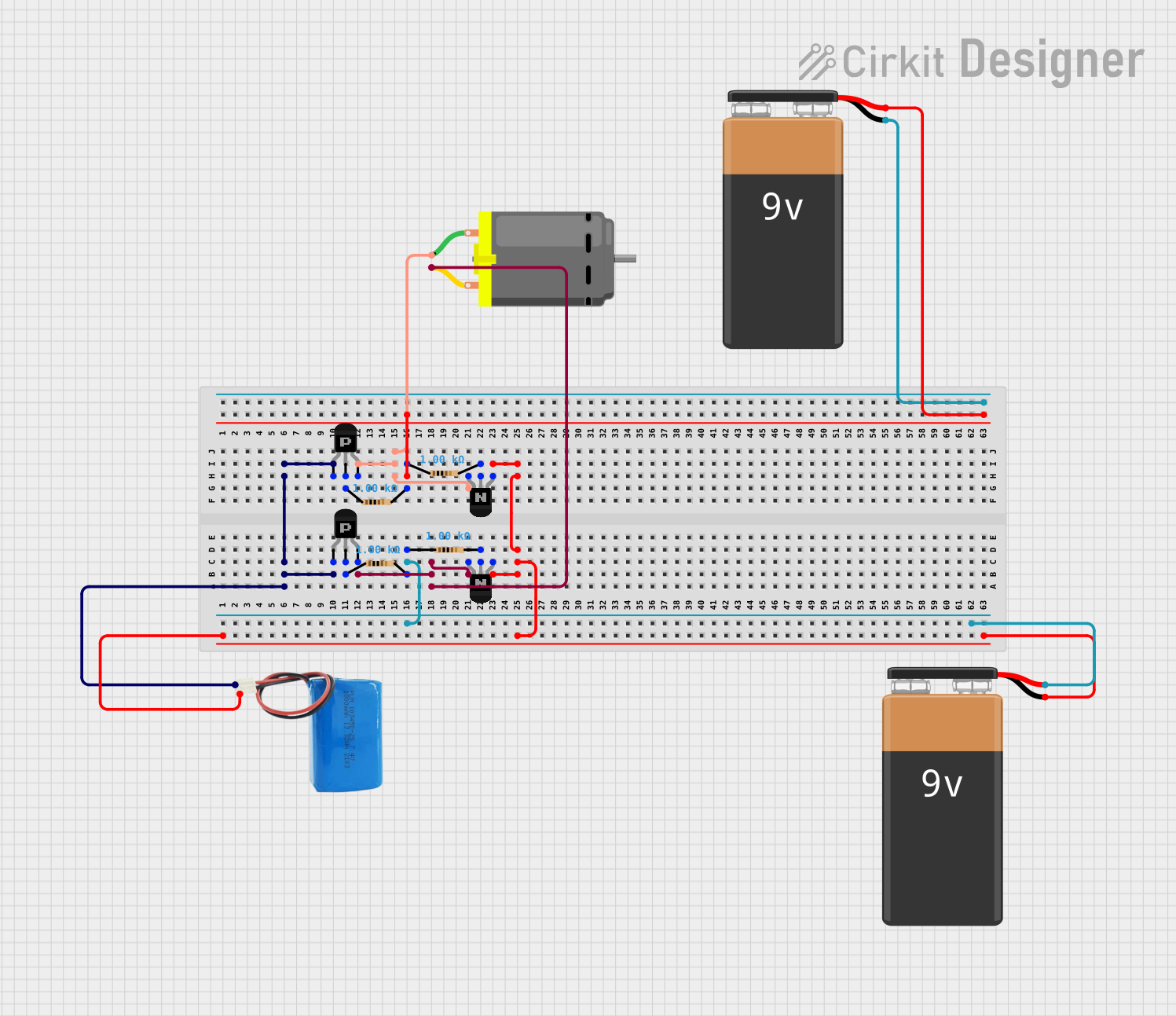
Explore Projects Built with NPN Transistor (EBC)
Technical Specifications
General Characteristics
- Type: NPN Bipolar Junction Transistor (BJT)
- Maximum Collector-Emitter Voltage (Vce): Specified by manufacturer (e.g., 40V)
- Maximum Collector-Base Voltage (Vcb): Specified by manufacturer (e.g., 60V)
- Maximum Emitter-Base Voltage (Veb): Specified by manufacturer (e.g., 6V)
- Maximum Collector Current (Ic): Specified by manufacturer (e.g., 200mA)
- Power Dissipation (Pd): Specified by manufacturer (e.g., 625mW)
Pin Configuration and Descriptions
| Pin Number | Name | Description |
|---|---|---|
| 1 | Emitter (E) | Emits carriers for conduction; usually connected to ground |
| 2 | Base (B) | Controls the transistor's operation; voltage applied here regulates the flow of current between emitter and collector |
| 3 | Collector (C) | Collects carriers from the emitter; connected to the load |
Usage Instructions
Incorporating into a Circuit
- Biasing the Transistor: Apply a small current to the base (B) to control the larger current between the collector (C) and emitter (E).
- Base Resistor Selection: Choose a base resistor to limit the base current (Ib) to a safe value that ensures the transistor operates in the desired region (active, saturation, or cutoff).
- Load Connection: Connect the load to the collector (C), with the other end of the load typically connected to the positive supply voltage.
- Emitter Grounding: Connect the emitter (E) to the ground of the circuit.
Best Practices
- Always check the maximum ratings of the transistor to prevent damage.
- Use a current-limiting resistor at the base to avoid excessive base current.
- Ensure proper heat sinking if the transistor is expected to dissipate significant power.
Example Circuit with Arduino UNO
// Example code to control an NPN transistor connected to an Arduino UNO

const int basePin = 9; // Base of the NPN transistor connected to PWM pin 9

void setup() {
  pinMode(basePin, OUTPUT); // Set the transistor base pin as an output
}

void loop() {
  analogWrite(basePin, 128); // Apply a base current via PWM (50% duty cycle)
  // This will turn the transistor on and off at a rate that allows for
  // an average current to flow from collector to emitter.
  delay(1000); // Wait for 1 second
  analogWrite(basePin, 0); // Turn off the transistor by setting base current to 0
  delay(1000); // Wait for 1 second
}
Troubleshooting and FAQs
Common Issues
- Transistor Not Switching: Ensure the base is receiving enough current to saturate the transistor.
- Excessive Heat: Check if the power dissipation exceeds the transistor's rating. Add a heat sink if necessary.
- Unexpected Operation: Verify that the pinout matches the EBC configuration and that connections are correct.
FAQs
Q: How do I know if my NPN transistor is working properly? A: Use a multimeter to check for continuity between the collector and emitter when the base is biased. There should be no continuity when the base is not biased.
Q: Can I use the NPN transistor to switch AC loads? A: No, BJTs are designed for DC applications. For AC loads, consider using a relay or a TRIAC.
Q: What happens if I reverse the collector and emitter? A: The transistor will not function correctly as the collector and emitter are doped differently and are not interchangeable.
Remember to always consult the specific datasheet for the NPN transistor model you are using, as the specifications can vary between different manufacturers and models.