How to Use MKE-S15 DS18B20 Waterproof Temperature Sensor: Examples, Pinouts, and Specs
Introduction
The MKE-S15 DS18B20 Waterproof Temperature Sensor is a precision digital thermometer that provides temperature readings which indicate the temperature of the device. Encased in a stainless steel housing, this sensor is waterproof and ideal for measuring temperature in liquids and harsh environments. It uses the DS18B20 sensor chip and communicates over a 1-Wire bus that by design requires only one data line (and ground) for communication with a central microprocessor.
Explore Projects Built with MKE-S15 DS18B20 Waterproof Temperature Sensor
Explore Projects Built with MKE-S15 DS18B20 Waterproof Temperature Sensor
Common Applications and Use Cases
- Aquariums and aquatic temperature monitoring
- Industrial systems and process control
- Environmental monitoring
- HVAC systems
- Food and beverage temperature tracking
Technical Specifications
Key Technical Details
- Supply Voltage: 3.0V to 5.5V
- Operating Temperature Range: -55°C to +125°C (-67°F to +257°F)
- Accuracy: ±0.5°C (from -10°C to +85°C)
- Output: Digital signal via 1-Wire bus
- Cable Length: Typically 1 meter (custom lengths available)
- Probe Material: Stainless steel
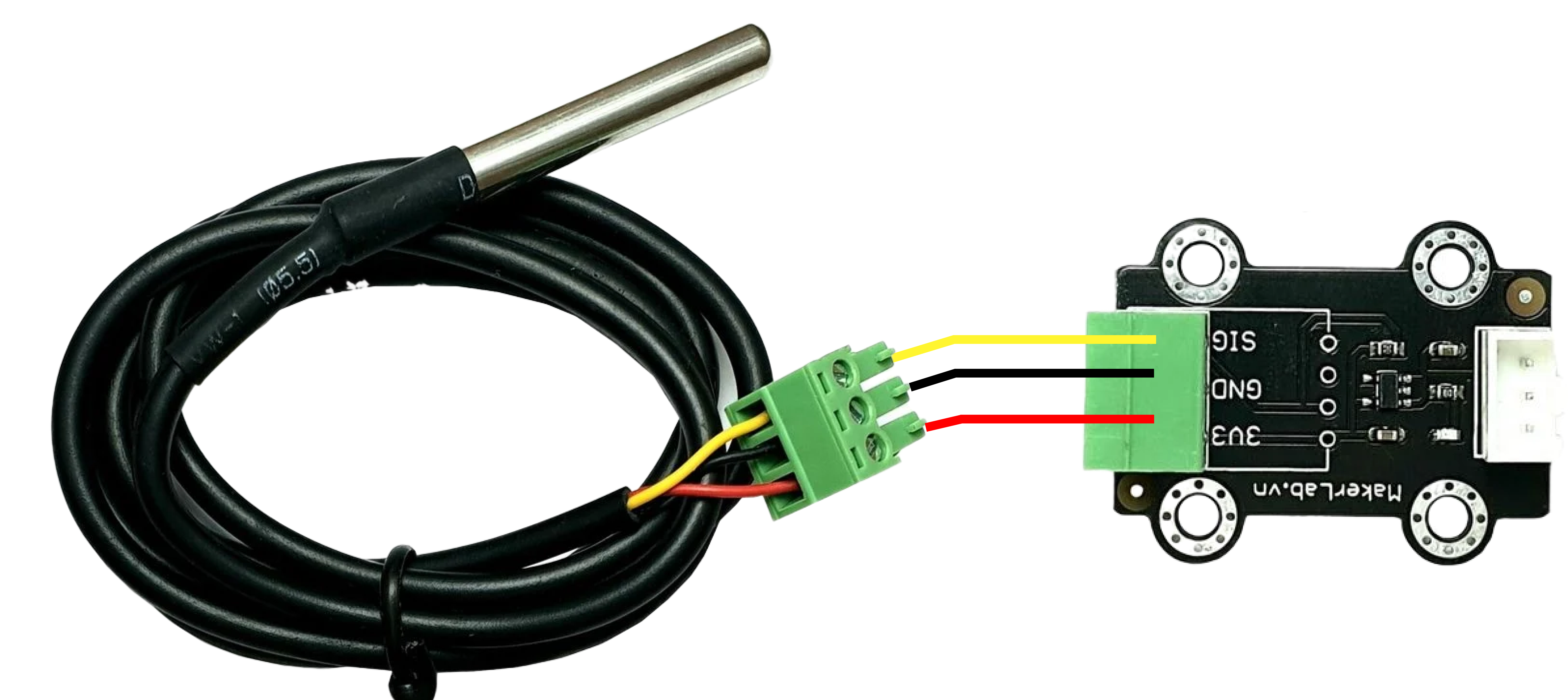
Pin Configuration and Descriptions
| Pin Number | Description | Color |
|---|---|---|
| 1 | Ground (GND) | Black |
| 2 | Data (DQ) | Yellow |
| 3 | Power Supply (VDD) | Red |
Usage Instructions
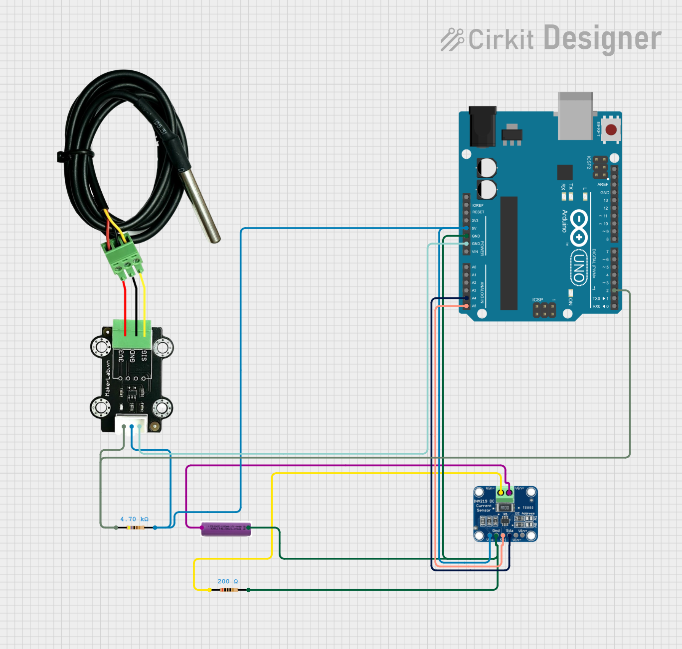
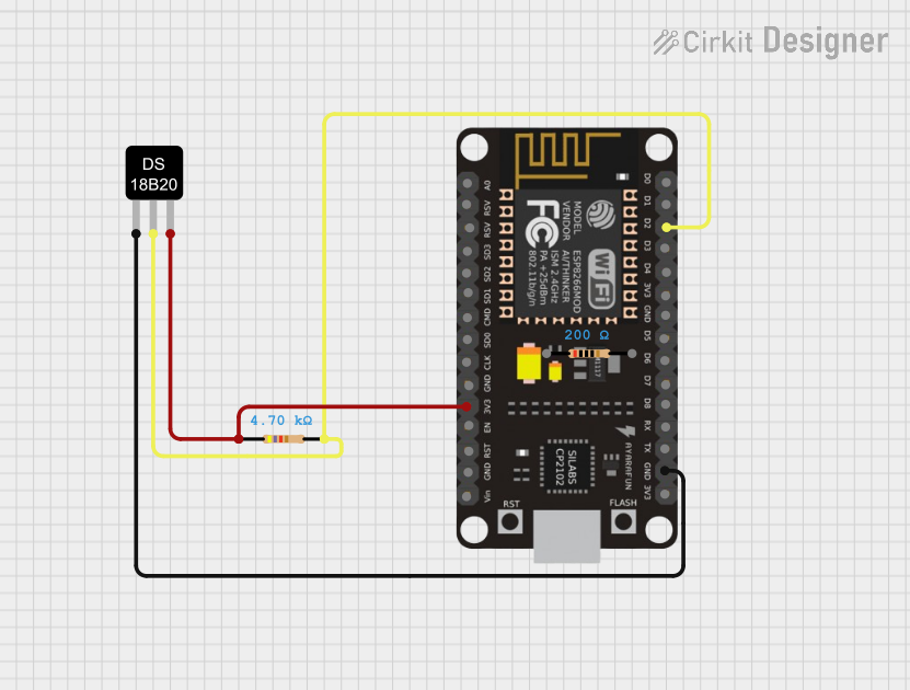
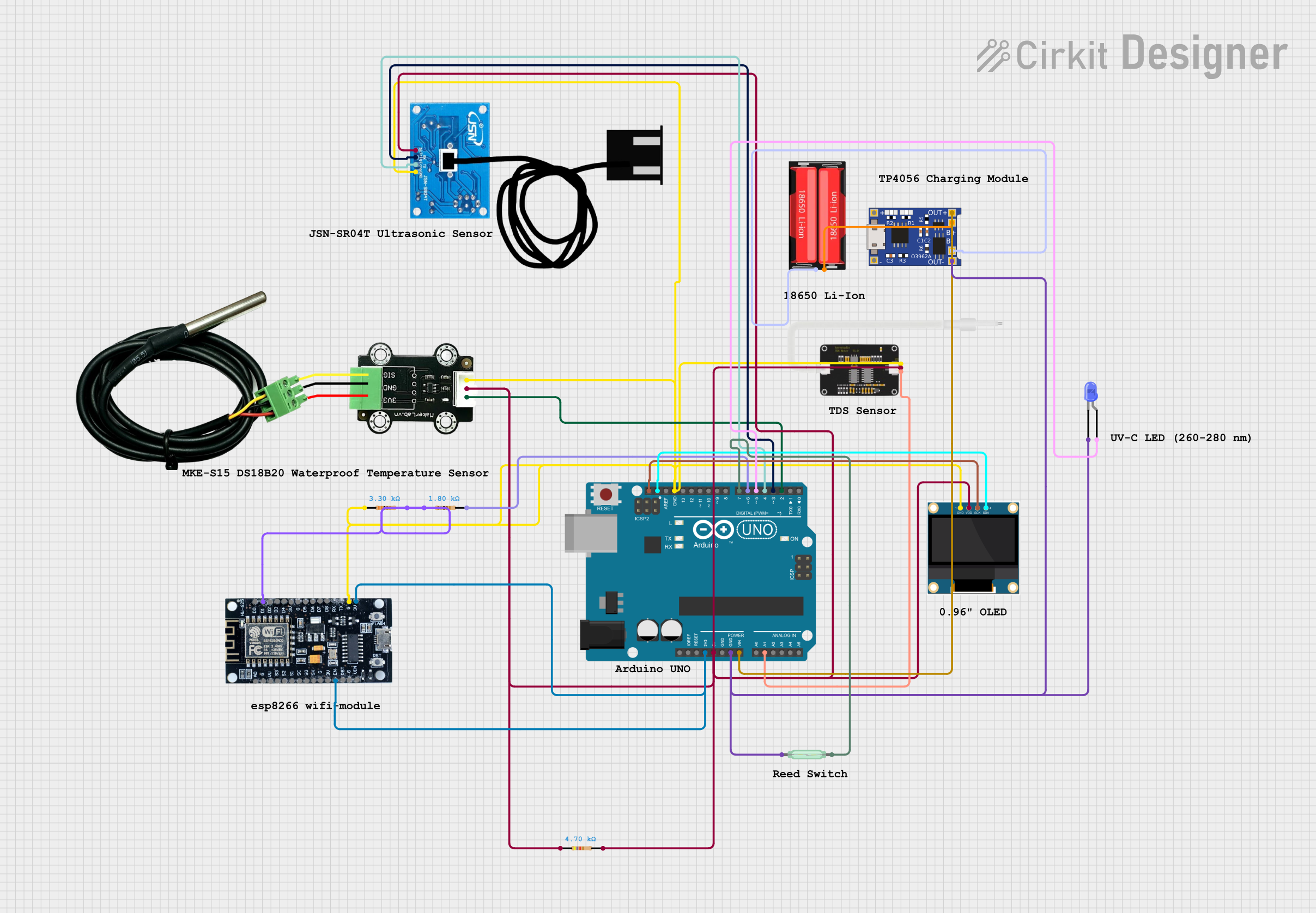
How to Use the Component in a Circuit
- Connect the Power Supply (VDD) to a 3.0V to 5.5V power source.
- Connect the Ground (GND) to the ground of the power source.
- Connect the Data (DQ) pin to a digital input on your microcontroller.
- If using parasitic power, tie the VDD pin to ground. Otherwise, provide power to the VDD pin.
- Add a 4.7kΩ pull-up resistor between the DQ line and VDD to ensure proper communication.
Important Considerations and Best Practices
- Ensure that the sensor is not subjected to temperatures beyond its specified range.
- Avoid bending the probe sharply, as this could damage the internal components.
- When using long cable lengths, be aware of potential signal degradation.
- For parasitic power configurations, ensure that your microcontroller can provide sufficient current on the data line.
Example Code for Arduino UNO
#include <OneWire.h>
#include <DallasTemperature.h>

// Data wire is plugged into pin 2 on the Arduino
#define ONE_WIRE_BUS 2

// Setup a oneWire instance to communicate with any OneWire devices
OneWire oneWire(ONE_WIRE_BUS);

// Pass our oneWire reference to Dallas Temperature sensor
DallasTemperature sensors(&oneWire);

void setup(void)
{
  // Start serial communication for debugging purposes
  Serial.begin(9600);
  // Start up the library
  sensors.begin();
}

void loop(void)
{
  // Call sensors.requestTemperatures() to issue a global temperature
  // request to all devices on the bus
  sensors.requestTemperatures();

  // Fetch the temperature in degrees Celsius for device index 0
  float tempC = sensors.getTempCByIndex(0);

  // Check if reading was successful
  if(tempC != DEVICE_DISCONNECTED_C)
  {
    Serial.print("Temperature: ");
    Serial.print(tempC);
    Serial.println("°C");
  }
  else
  {
    Serial.println("Error: Could not read temperature data");
  }

  delay(1000); // Wait 1 second before next reading
}
Troubleshooting and FAQs
Common Issues Users Might Face
- Inaccurate Temperature Readings: Ensure the pull-up resistor is correctly placed and that the sensor is not exposed to rapid temperature changes.
- No Data on Serial Monitor: Check all connections, ensure the correct COM port is selected, and that the baud rate matches the
Serial.beginsetting in your code. - Sensor Not Detected: Verify that the sensor is correctly wired and that the OneWire bus is properly initialized in your code.
Solutions and Tips for Troubleshooting
- Double-check wiring, especially the pull-up resistor on the data line.
- Use the
OneWirelibrary's search function to confirm device presence on the bus. - Ensure that the sensor's stainless steel housing is not in contact with any conductive material that could cause a short circuit.
FAQs
Q: Can I connect multiple DS18B20 sensors to the same microcontroller? A: Yes, the DS18B20 supports multiple devices on the same 1-Wire bus.
Q: How long can the sensor cable be? A: The cable length can be up to 100 meters, but it may require a lower pull-up resistor value for longer distances.
Q: Is calibration required for this sensor? A: The DS18B20 is factory-calibrated and does not typically require additional calibration.