Cirkit Designer Logo
Cirkit Designer
Your all-in-one circuit design IDE
Home / 
Component Documentation

How to Use MAX1704X: Examples, Pinouts, and Specs

Image of MAX1704X
Cirkit Designer LogoDesign with MAX1704X in Cirkit Designer

Introduction

The MAX1704X voltage regulator is a compact, adjustable output voltage regulator designed for a wide range of electronic applications. Its ability to provide a stable output voltage makes it ideal for use in power supply circuits, battery-operated devices, and any application where a regulated voltage is required to ensure the proper operation of electronic components.

Explore Projects Built with MAX1704X

Use Cirkit Designer to design, explore, and prototype these projects online. Some projects support real-time simulation. Click "Open Project" to start designing instantly!
Battery-Powered Health Monitoring System with Nucleo WB55RG and OLED Display
Image of Pulsefex: A project utilizing MAX1704X in a practical application
This circuit is a multi-sensor data acquisition system that uses a Nucleo WB55RG microcontroller to interface with a digital temperature sensor (TMP102), a pulse oximeter and heart-rate sensor (MAX30102), and a 0.96" OLED display via I2C. Additionally, it includes a Sim800l module for GSM communication, powered by a 3.7V LiPo battery.
Cirkit Designer LogoOpen Project in Cirkit Designer
ESP32-Based Multi-Sensor Health Monitoring System with Bluetooth Connectivity
Image of circuit diagram: A project utilizing MAX1704X in a practical application
This circuit features an ESP32-WROOM-32UE microcontroller as the central processing unit, interfacing with a variety of sensors and modules. It includes a MAX30100 pulse oximeter and heart-rate sensor, an MLX90614 infrared thermometer, an HC-05 Bluetooth module for wireless communication, and a Neo 6M GPS module for location tracking. All components are powered by a common voltage supply and are connected to specific GPIO pins on the ESP32 for data exchange, with the sensors using I2C communication and the modules using UART.
Cirkit Designer LogoOpen Project in Cirkit Designer
Arduino Mega 2560-Based Health Monitoring System with Temperature, Heart Rate, and Load Cell Sensors
Image of Major Project: A project utilizing MAX1704X in a practical application
This circuit is designed to interface a Mega 2560 R3 microcontroller with various sensors, including an MLX90614 infrared temperature sensor, a MAX30102 pulse oximeter, and an HX711 load cell amplifier connected to a load cell. The microcontroller reads data from these sensors to perform measurements such as temperature, heart rate, and weight.
Cirkit Designer LogoOpen Project in Cirkit Designer
Arduino Mega 2560 Based Multi-Channel Thermocouple Reader
Image of thermostat-test: A project utilizing MAX1704X in a practical application
This circuit is designed to interface with multiple MAX6675 thermocouple-to-digital converter modules using an Arduino Mega 2560 as the central processing unit. The Arduino reads temperature data from the MAX6675 modules over a shared SPI bus, with individual chip select (CS) lines for each module to enable multiplexing. The circuit is likely used for monitoring multiple temperature points, possibly in an industrial setting where precise temperature control and monitoring are critical.
Cirkit Designer LogoOpen Project in Cirkit Designer

Explore Projects Built with MAX1704X

Use Cirkit Designer to design, explore, and prototype these projects online. Some projects support real-time simulation. Click "Open Project" to start designing instantly!
Image of Pulsefex: A project utilizing MAX1704X in a practical application
Battery-Powered Health Monitoring System with Nucleo WB55RG and OLED Display
This circuit is a multi-sensor data acquisition system that uses a Nucleo WB55RG microcontroller to interface with a digital temperature sensor (TMP102), a pulse oximeter and heart-rate sensor (MAX30102), and a 0.96" OLED display via I2C. Additionally, it includes a Sim800l module for GSM communication, powered by a 3.7V LiPo battery.
Cirkit Designer LogoOpen Project in Cirkit Designer
Image of circuit diagram: A project utilizing MAX1704X in a practical application
ESP32-Based Multi-Sensor Health Monitoring System with Bluetooth Connectivity
This circuit features an ESP32-WROOM-32UE microcontroller as the central processing unit, interfacing with a variety of sensors and modules. It includes a MAX30100 pulse oximeter and heart-rate sensor, an MLX90614 infrared thermometer, an HC-05 Bluetooth module for wireless communication, and a Neo 6M GPS module for location tracking. All components are powered by a common voltage supply and are connected to specific GPIO pins on the ESP32 for data exchange, with the sensors using I2C communication and the modules using UART.
Cirkit Designer LogoOpen Project in Cirkit Designer
Image of Major Project: A project utilizing MAX1704X in a practical application
Arduino Mega 2560-Based Health Monitoring System with Temperature, Heart Rate, and Load Cell Sensors
This circuit is designed to interface a Mega 2560 R3 microcontroller with various sensors, including an MLX90614 infrared temperature sensor, a MAX30102 pulse oximeter, and an HX711 load cell amplifier connected to a load cell. The microcontroller reads data from these sensors to perform measurements such as temperature, heart rate, and weight.
Cirkit Designer LogoOpen Project in Cirkit Designer
Image of thermostat-test: A project utilizing MAX1704X in a practical application
Arduino Mega 2560 Based Multi-Channel Thermocouple Reader
This circuit is designed to interface with multiple MAX6675 thermocouple-to-digital converter modules using an Arduino Mega 2560 as the central processing unit. The Arduino reads temperature data from the MAX6675 modules over a shared SPI bus, with individual chip select (CS) lines for each module to enable multiplexing. The circuit is likely used for monitoring multiple temperature points, possibly in an industrial setting where precise temperature control and monitoring are critical.
Cirkit Designer LogoOpen Project in Cirkit Designer

Common Applications and Use Cases

  • Power supplies for electronic devices
  • Battery chargers and management systems
  • Voltage regulation for microcontrollers and digital circuits
  • Portable electronics requiring stable power supply
  • Automotive electronics for regulating sensor and accessory voltages

Technical Specifications

The MAX1704X voltage regulator's technical specifications are crucial for ensuring compatibility and optimal performance in electronic circuits.

Key Technical Details

  • Input Voltage Range: 4.5V to 28V
  • Output Voltage Range: Adjustable from 1.25V to 27V
  • Output Current: Up to 1.5A (with proper heat sinking)
  • Quiescent Current: Typically 5mA
  • Temperature Range: -40°C to +125°C

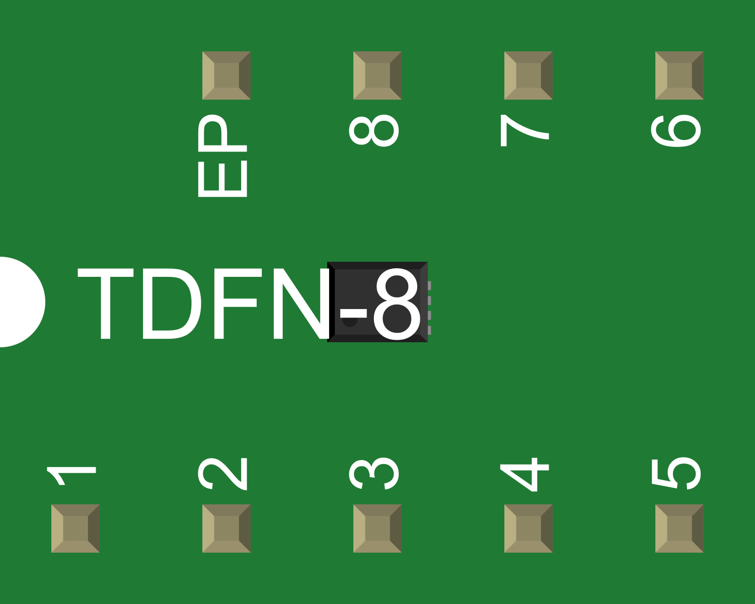
Pin Configuration and Descriptions

Pin Number Name Description
1 IN Input voltage supply. Connect to the source voltage.
2 OUT Regulated output voltage. Connect to the load.
3 ADJ Adjustable pin to set the output voltage. Connect to a resistor divider network.
4 GND Ground reference for the regulator. Connect to the system ground.

Usage Instructions

How to Use the MAX1704X in a Circuit

  1. Connect the Input Voltage: Apply the source voltage to the IN pin, ensuring it is within the specified input voltage range.
  2. Set the Output Voltage: Connect a resistor divider network between the OUT, ADJ, and GND pins to set the desired output voltage.
  3. Connect the Load: Attach the load to the OUT pin.
  4. Capacitors for Stability: Place a capacitor between the IN and GND pins and another between the OUT and GND pins to ensure stability and reduce noise.

Important Considerations and Best Practices

  • Always verify that the input voltage does not exceed the maximum rating.
  • Use capacitors with low equivalent series resistance (ESR) for better performance.
  • Ensure that the output current does not exceed the maximum rating, considering thermal limitations.
  • Provide adequate heat sinking if the regulator is expected to dissipate significant power.
  • Avoid long wire runs between the regulator and the load to minimize voltage drops and noise.

Troubleshooting and FAQs

Common Issues

  • Output Voltage Fluctuation: Ensure capacitors are correctly placed and are of the recommended value.
  • Overheating: Check if the current draw is within the limit and improve heat sinking if necessary.
  • No Output Voltage: Verify connections, input voltage, and the resistor divider network.

Solutions and Tips for Troubleshooting

  • Double-check the wiring and solder joints for any shorts or opens.
  • Measure the input voltage to ensure it is within the specified range.
  • Use a multimeter to verify the resistor values in the divider network.
  • If the regulator overheats, reduce the load current or improve heat dissipation.

FAQs

Q: Can I use the MAX1704X without an adjustable resistor network? A: Yes, but the output voltage will be fixed based on the internal reference voltage.

Q: What is the maximum power dissipation of the MAX1704X? A: The maximum power dissipation depends on the input voltage, output voltage, load current, and thermal resistance of the heat sink.

Q: How do I calculate the resistor values for a specific output voltage? A: Use the formula provided in the datasheet, typically involving the reference voltage and desired output voltage.

Example Connection with Arduino UNO

// No direct code is required for the MAX1704X as it is a hardware component.
// However, you can monitor the output voltage using an Arduino UNO by reading the voltage through an analog pin.

const int analogPin = A0; // Connect the OUT pin of MAX1704X to A0 on Arduino

void setup() {
  Serial.begin(9600);
}

void loop() {
  int sensorValue = analogRead(analogPin); // Read the voltage
  float voltage = sensorValue * (5.0 / 1023.0); // Convert to voltage
  Serial.println(voltage); // Print the voltage to the Serial Monitor
  delay(1000); // Wait for a second
}

Note: The code above assumes that the output voltage of the MAX1704X is within the 0-5V range that the Arduino can measure. If the voltage is higher, a voltage divider network is required to bring the voltage within the Arduino's measurement range.