How to Use DC-DC Boost -1: Examples, Pinouts, and Specs
Introduction
A DC-DC boost converter is a power converter that steps up (increases) the input voltage to a higher output voltage while maintaining the same polarity. It is commonly used in applications where a higher voltage is required from a lower voltage source.
Explore Projects Built with DC-DC Boost -1


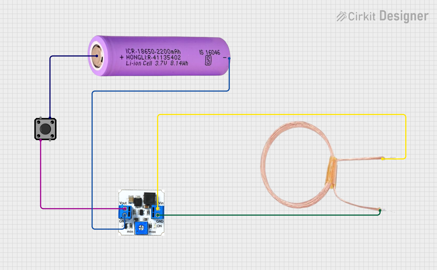
Explore Projects Built with DC-DC Boost -1
Common Applications and Use Cases:
- Powering high-voltage devices from low-voltage batteries (e.g., 3.7V Li-ion batteries).
- Solar power systems to step up panel voltage for charging batteries or powering devices.
- LED drivers for high-power LEDs requiring higher voltages.
- Portable electronics and USB-powered devices requiring higher voltage outputs.
Technical Specifications
Below are the key technical details for a typical DC-DC boost converter module:
| Parameter | Specification |
|---|---|
| Input Voltage Range | 3V to 32V |
| Output Voltage Range | 5V to 35V |
| Maximum Output Current | 2A (varies by model, check datasheet) |
| Efficiency | Up to 90% |
| Switching Frequency | 150 kHz |
| Operating Temperature | -40°C to +85°C |
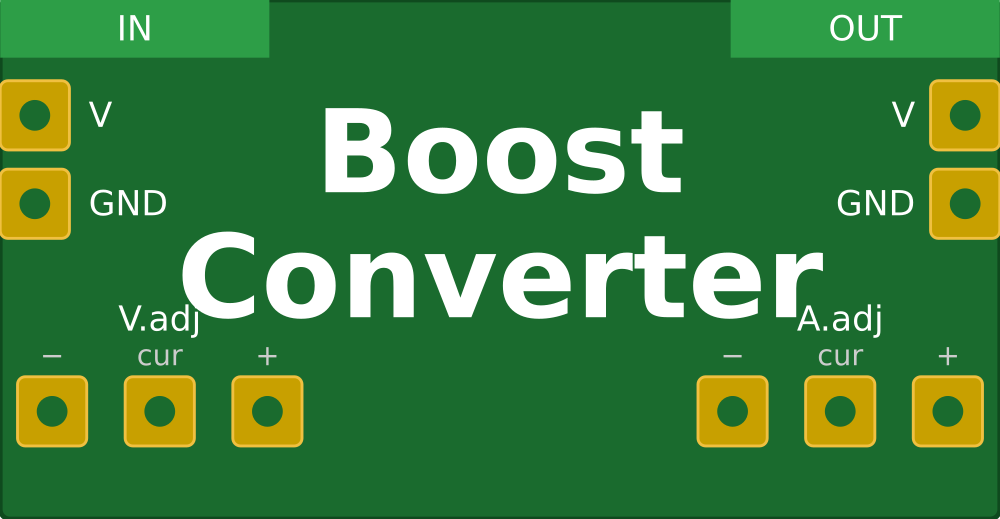
Pin Configuration and Descriptions
| Pin Name | Description |
|---|---|
| VIN | Input voltage pin. Connect the positive terminal of the input power source here. |
| GND | Ground pin. Connect the negative terminal of the input power source here. |
| VOUT | Output voltage pin. Provides the boosted voltage to the load. |
| ADJ (optional) | Adjustment pin for setting the output voltage (on adjustable models). |
Usage Instructions
How to Use the DC-DC Boost Converter in a Circuit:
Connect the Input Voltage:
- Connect the positive terminal of your power source to the
VINpin. - Connect the negative terminal of your power source to the
GNDpin.
- Connect the positive terminal of your power source to the
Set the Output Voltage (if adjustable):
- Use a small screwdriver to turn the potentiometer on the module.
- Turn clockwise to increase the output voltage or counterclockwise to decrease it.
- Use a multimeter to measure the output voltage at the
VOUTpin while adjusting.
Connect the Load:
- Connect the positive terminal of your load to the
VOUTpin. - Connect the negative terminal of your load to the
GNDpin.
- Connect the positive terminal of your load to the
Power On:
- Turn on the input power source. The module will boost the input voltage to the desired output voltage.
Important Considerations and Best Practices:
- Input Voltage Range: Ensure the input voltage is within the specified range (e.g., 3V to 32V). Exceeding this range may damage the module.
- Output Voltage Setting: Always set the output voltage before connecting the load to avoid overvoltage damage.
- Heat Dissipation: For high current loads, the module may heat up. Use a heatsink or active cooling if necessary.
- Current Limit: Do not exceed the maximum output current rating of the module to prevent overheating or failure.
- Polarity: Double-check the polarity of your connections. Reversing the input or output connections can damage the module.
Example: Using the DC-DC Boost Converter with an Arduino UNO
Below is an example of powering a 12V device (e.g., a motor) using a DC-DC boost converter and an Arduino UNO:
Circuit Connections:
- Connect a 5V power source (e.g., USB or battery) to the
VINandGNDpins of the boost converter. - Adjust the output voltage to 12V using the potentiometer.
- Connect the
VOUTpin of the boost converter to the positive terminal of the motor. - Connect the negative terminal of the motor to the
GNDpin of the boost converter.
Arduino Code Example:
// Example code to control a motor powered by a DC-DC boost converter
// connected to an Arduino UNO. The motor is controlled via a PWM signal.

const int motorPin = 9; // PWM pin connected to motor driver or transistor

void setup() {
  pinMode(motorPin, OUTPUT); // Set motor pin as output
}

void loop() {
  analogWrite(motorPin, 128); // Set motor speed to 50% (PWM value: 128/255)
  delay(5000); // Run motor for 5 seconds

  analogWrite(motorPin, 0); // Stop motor
  delay(2000); // Wait for 2 seconds before restarting
}
Troubleshooting and FAQs
Common Issues and Solutions:
No Output Voltage:
- Cause: Input power source is not connected or is below the minimum input voltage.
- Solution: Verify the input voltage and connections. Ensure the input voltage is within the specified range.
Output Voltage is Incorrect:
- Cause: Potentiometer is not adjusted correctly.
- Solution: Use a multimeter to measure the output voltage and adjust the potentiometer as needed.
Module Overheating:
- Cause: Exceeding the maximum current rating or poor heat dissipation.
- Solution: Reduce the load current or add a heatsink to the module.
Load Not Powering On:
- Cause: Output voltage is too low or connections are incorrect.
- Solution: Verify the output voltage and ensure proper connections to the load.
FAQs:
Q: Can I use the DC-DC boost converter with a 3.7V Li-ion battery?
- A: Yes, as long as the battery voltage is within the input range of the module and the load current does not exceed the module's capacity.
Q: How do I calculate the efficiency of the boost converter?
- A: Efficiency (%) = (Output Power / Input Power) × 100. Measure the input and output voltage and current to calculate power.
Q: Can I use this module to power sensitive electronics?
- A: Yes, but ensure the output voltage is stable and within the tolerance range of your device. Adding a capacitor at the output may help reduce voltage ripple.
Q: What happens if I reverse the input polarity?
- A: Most modules do not have reverse polarity protection and may be permanently damaged. Always double-check your connections.