How to Use X-404 Controlbyweb: Examples, Pinouts, and Specs
Introduction
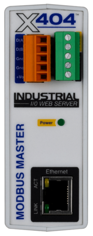
The X-404 Controlbyweb is a versatile, web-based relay controller designed for remote control and monitoring of devices over the internet. It features multiple relay outputs, digital inputs, and supports integration with various sensors and systems, making it ideal for automation and control applications. With its built-in web server, the X-404 allows users to configure, monitor, and control devices through a standard web browser without requiring additional software.
Explore Projects Built with X-404 Controlbyweb
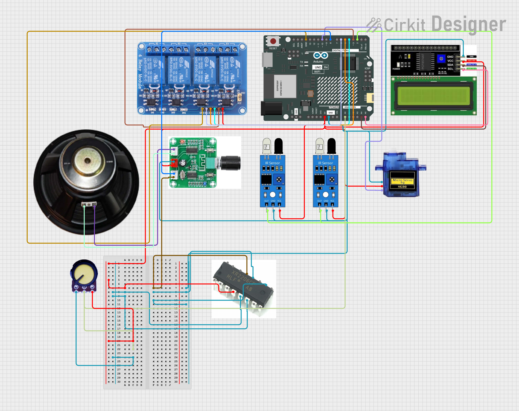
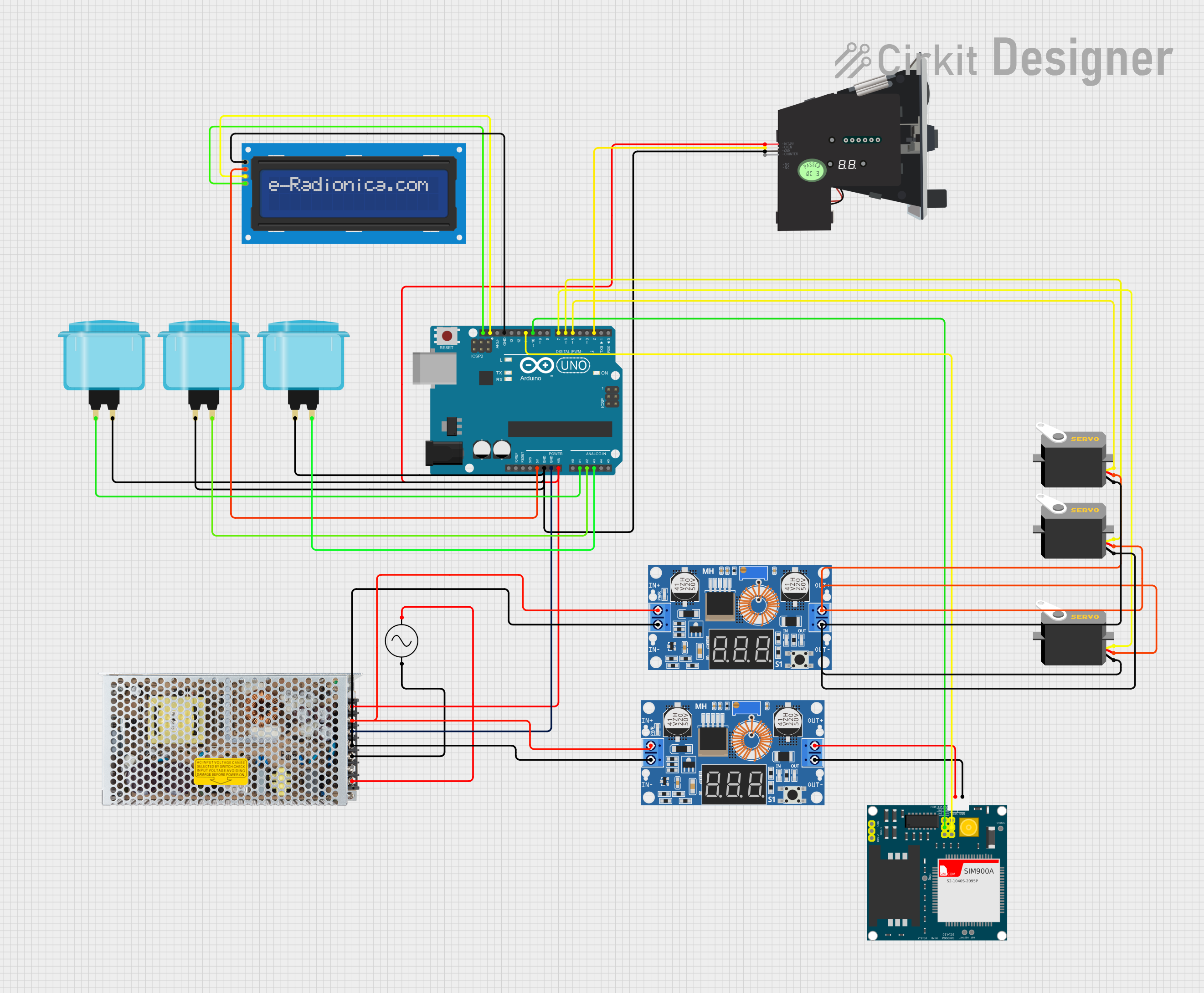

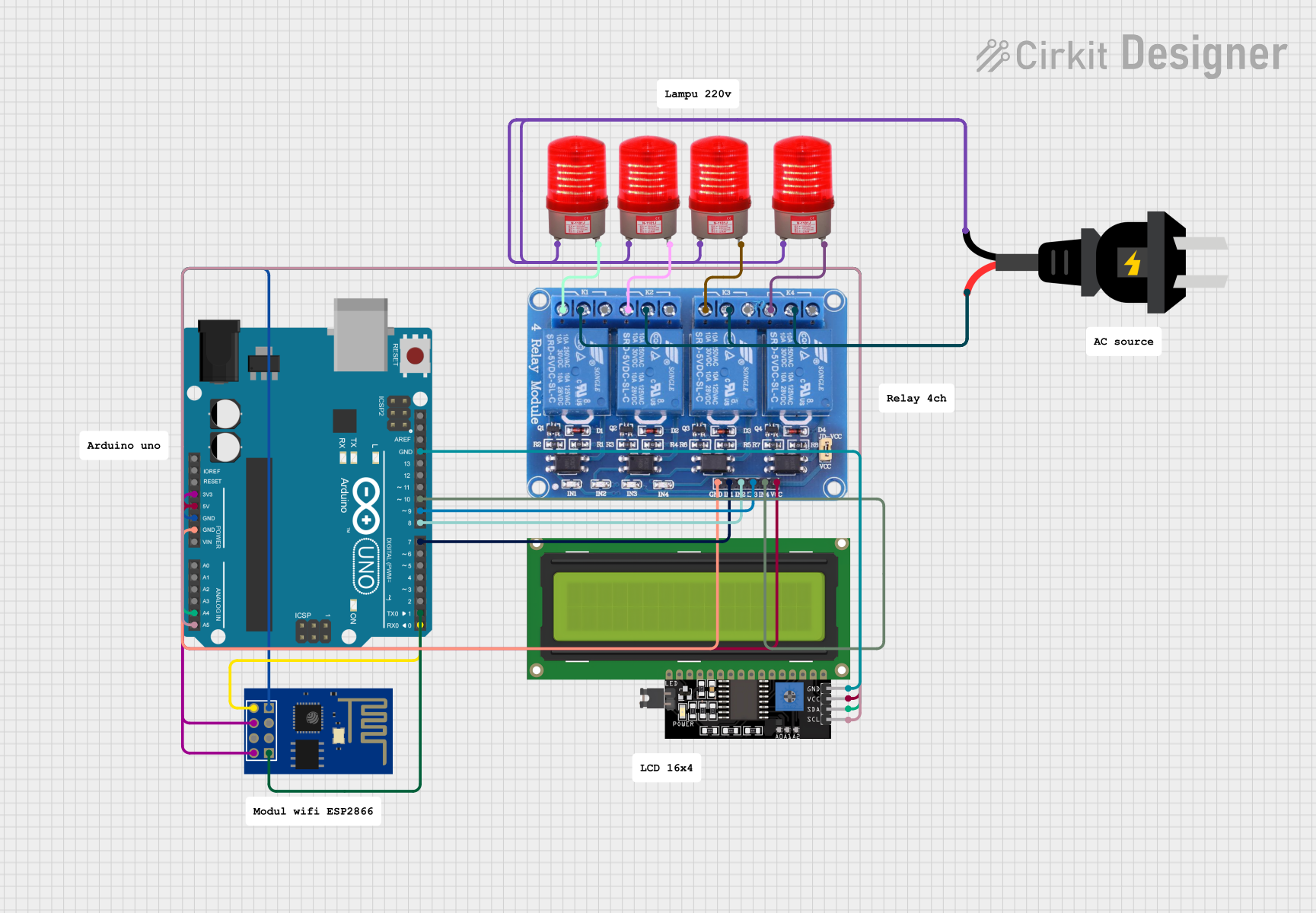
Explore Projects Built with X-404 Controlbyweb
Common Applications and Use Cases
- Home automation (e.g., controlling lights, HVAC systems, or appliances)
- Industrial automation and process control
- Remote monitoring of sensors and equipment
- Security systems and access control
- Agricultural automation (e.g., irrigation systems)
- Data logging and environmental monitoring
Technical Specifications
The X-404 Controlbyweb is equipped with robust features to meet a wide range of automation needs. Below are its key technical specifications:
General Specifications
| Parameter | Specification |
|---|---|
| Power Supply | 9-28 VDC |
| Power Consumption | 1.5 W (typical) |
| Communication Interface | Ethernet (10/100 Mbps) |
| Operating Temperature | -40°C to 65°C (-40°F to 149°F) |
| Dimensions | 4.5" x 3.3" x 1.1" (114mm x 84mm x 28mm) |
Relay Outputs
| Parameter | Specification |
|---|---|
| Number of Relays | 4 |
| Relay Type | SPDT (Single Pole Double Throw) |
| Contact Rating | 5A @ 30VDC or 5A @ 250VAC |
| Isolation | 1500 VAC |
Digital Inputs
| Parameter | Specification |
|---|---|
| Number of Inputs | 4 |
| Input Type | Dry contact or logic-level input |
| Voltage Range | 0-5 VDC (logic-level input) |
Pin Configuration
The X-404 features a terminal block for connecting relays, inputs, and power. Below is the pin configuration:
| Pin Number | Function | Description |
|---|---|---|
| 1 | Relay 1 Common | Common terminal for Relay 1 |
| 2 | Relay 1 Normally Open | Normally open terminal for Relay 1 |
| 3 | Relay 1 Normally Closed | Normally closed terminal for Relay 1 |
| 4-6 | Relay 2 Connections | Similar to Relay 1 |
| 7-9 | Relay 3 Connections | Similar to Relay 1 |
| 10-12 | Relay 4 Connections | Similar to Relay 1 |
| 13 | Digital Input 1 | Connect to dry contact or logic input |
| 14 | Digital Input 2 | Connect to dry contact or logic input |
| 15 | Digital Input 3 | Connect to dry contact or logic input |
| 16 | Digital Input 4 | Connect to dry contact or logic input |
| 17 | Power (+) | Positive terminal for power supply |
| 18 | Power (-) | Negative terminal for power supply |
Usage Instructions
How to Use the X-404 in a Circuit
- Power Connection: Connect a 9-28 VDC power supply to the power terminals (Pin 17 for + and Pin 18 for -).
- Relay Connections: Wire the devices you want to control to the relay terminals. For example:
- Connect the load to the "Common" and "Normally Open" terminals if you want the relay to close the circuit when activated.
- Use the "Normally Closed" terminal if you want the circuit to be closed by default and open when the relay is activated.
- Digital Inputs: Connect sensors or switches to the digital input terminals. Ensure the input voltage does not exceed 5 VDC for logic-level inputs.
- Network Setup: Connect the X-404 to your local network using an Ethernet cable. Access the device's web interface by entering its IP address in a web browser.
- Configuration: Use the web interface to configure relay behavior, input monitoring, and automation rules.
Important Considerations and Best Practices
- Ensure the power supply voltage is within the specified range to avoid damage to the device.
- Use proper isolation and grounding techniques when connecting high-voltage loads to the relays.
- Secure the device on a stable surface to prevent accidental disconnections.
- Change the default login credentials in the web interface to enhance security.
- Regularly update the firmware to access new features and security patches.
Example: Controlling the X-404 with an Arduino UNO
The X-404 can be controlled via HTTP requests. Below is an example Arduino sketch to toggle a relay:
#include <SPI.h>
#include <Ethernet.h>

// Enter the MAC address and IP address of your Arduino
byte mac[] = { 0xDE, 0xAD, 0xBE, 0xEF, 0xFE, 0xED };
IPAddress ip(192, 168, 1, 177);

// Enter the IP address of the X-404
IPAddress x404_ip(192, 168, 1, 100);

// Initialize Ethernet client
EthernetClient client;

void setup() {
  // Start Ethernet connection
  Ethernet.begin(mac, ip);
  Serial.begin(9600);
  delay(1000); // Allow time for Ethernet to initialize
}

void loop() {
  // Send HTTP request to toggle Relay 1
  if (client.connect(x404_ip, 80)) {
    Serial.println("Connected to X-404");
    client.println("GET /relay/1/toggle HTTP/1.1");
    client.println("Host: 192.168.1.100"); // Replace with X-404 IP
    client.println("Connection: close");
    client.println();
    client.stop();
  } else {
    Serial.println("Connection failed");
  }
  delay(5000); // Wait 5 seconds before sending the next request
}
Note: Replace 192.168.1.100 with the actual IP address of your X-404 device.
Troubleshooting and FAQs
Common Issues and Solutions
Cannot Access Web Interface
- Cause: Incorrect IP address or network configuration.
- Solution: Ensure the X-404 is connected to the network and check its IP address using a network scanner.
Relays Not Activating
- Cause: Incorrect wiring or insufficient power supply.
- Solution: Verify the relay connections and ensure the power supply meets the required specifications.
Digital Inputs Not Responding
- Cause: Incorrect input voltage or wiring.
- Solution: Ensure the input voltage is within the 0-5 VDC range and check the wiring.
Device Not Responding to HTTP Requests
- Cause: Network issues or incorrect request format.
- Solution: Verify the network connection and ensure the HTTP request syntax is correct.
FAQs
Q: Can the X-404 be used without an internet connection?
A: Yes, the X-404 can operate on a local network without internet access.
Q: How many devices can I control with the X-404?
A: The X-404 has 4 relay outputs, allowing you to control up to 4 devices.
Q: Is the X-404 compatible with third-party sensors?
A: Yes, the X-404 supports integration with various sensors via its digital inputs.
Q: Can I schedule relay operations?
A: Yes, the X-404 includes a scheduling feature accessible through its web interface.