How to Use TCN4S: Examples, Pinouts, and Specs
Introduction
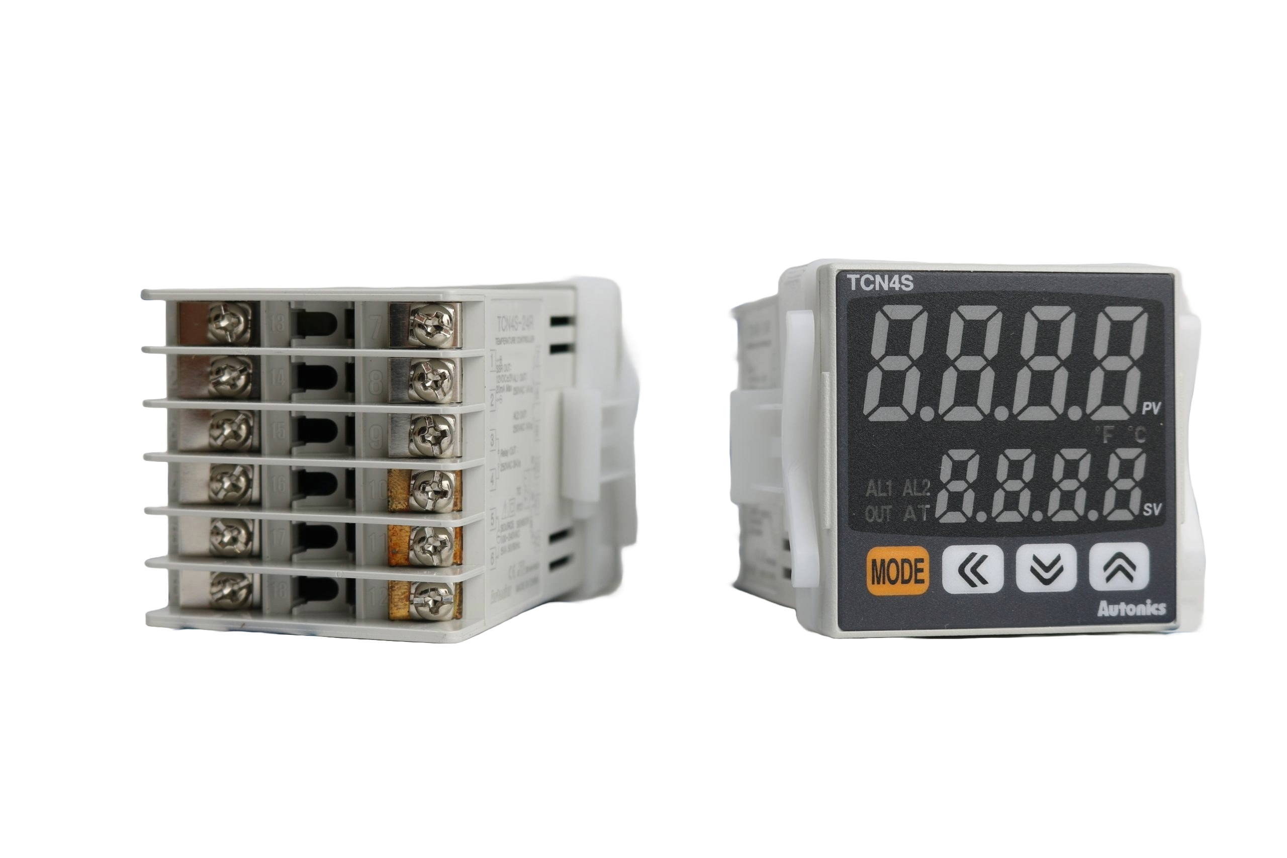
The TCN4S is a sophisticated thermocouple temperature controller that utilizes Proportional-Integral-Derivative (PID) control to ensure precise temperature regulation. This electronic component is designed for a wide range of industrial applications, including plastic injection molding machines, packaging machines, and ovens. Its ability to maintain a stable temperature environment makes it an essential device in processes where temperature accuracy is critical.
Explore Projects Built with TCN4S


Explore Projects Built with TCN4S
Technical Specifications
General Specifications
- Control Method: PID / On-Off / Manual
- Input Type: Thermocouple (TC), Resistance Temperature Detector (RTD)
- Output Signal: Relay, SSR, Current (4-20 mA)
- Supply Voltage: 100-240VAC, 50/60Hz
- Power Consumption: Less than 5 VA
- Operating Temperature: 0°C to 50°C
- Storage Temperature: -20°C to 60°C
- Humidity: 35 to 85% RH
Pin Configuration and Descriptions
| Pin Number | Description | Notes |
|---|---|---|
| 1 | Power Supply (+) | Connect to 100-240VAC |
| 2 | Power Supply (-) | |
| 3 | Relay Output | NO (Normally Open) contact |
| 4 | Relay Output Common | |
| 5 | Relay Output | NC (Normally Closed) contact |
| 6 | SSR Output (+) | Connect to Solid State Relay |
| 7 | SSR Output (-) | |
| 8 | Input Signal (+) | Connect to thermocouple + |
| 9 | Input Signal (-) | Connect to thermocouple - |
| 10 | Current Output (4-20 mA) | For external control or display |
Usage Instructions
Wiring the TCN4S
- Power Supply: Connect the power supply terminals (pins 1 and 2) to a 100-240VAC source.
- Thermocouple Connection: Attach the thermocouple leads to the input signal terminals (pins 8 and 9), ensuring correct polarity.
- Output Configuration: Choose the appropriate output for your application:
- For a relay output, connect your load to the relay output terminals (pins 3, 4, and 5).
- For SSR control, connect the SSR input to the SSR output terminals (pins 6 and 7).
- For a current output, connect the external device to the current output terminal (pin 10).
Programming and Operation
- Setpoint Adjustment: Use the front panel buttons to set the desired temperature setpoint.
- PID Tuning: If necessary, adjust the PID parameters to optimize the temperature control for your specific application.
- Manual/Auto Mode: Switch between manual and automatic modes as required for your process control.
Best Practices
- Ensure proper heat dissipation from the controller by providing adequate ventilation.
- Use shielded cables for thermocouple connections to minimize electrical noise.
- Regularly calibrate the controller to maintain accuracy.
Troubleshooting and FAQs
Common Issues
- Temperature Overshoot: Adjust the PID settings to reduce aggressive heating or cooling.
- Display Errors: Check the thermocouple connections and ensure the correct input type is selected.
- Output Not Activating: Verify the wiring and settings for the selected output type.
FAQs
Q: Can the TCN4S be used with any type of thermocouple? A: The TCN4S is compatible with several common thermocouple types. Refer to the manual for the specific types supported.
Q: How do I calibrate the TCN4S? A: Calibration procedures are outlined in the user manual. It typically involves comparing the controller reading to a known temperature reference and adjusting the offset.
Q: What should I do if the controller is not responding to input changes? A: Check the input wiring and ensure the controller is configured for the correct input type. If the issue persists, reset the controller to factory settings.
For more detailed troubleshooting, refer to the manufacturer's manual or contact technical support.
Example Arduino Connection (Optional)
If you wish to integrate the TCN4S with an Arduino UNO for data logging or additional control functionality, you can do so by connecting the current output (4-20 mA) to an analog input on the Arduino using a suitable current-to-voltage converter circuit.
// Example code for reading a 4-20mA signal from TCN4S with an Arduino UNO
int sensorPin = A0; // Select the input pin for the TCN4S current output
int sensorValue = 0; // Variable to store the value coming from the sensor

void setup() {
  Serial.begin(9600); // Start serial communication at 9600 baud
}

void loop() {
  sensorValue = analogRead(sensorPin); // Read the value from the sensor
  // Convert the analog reading (which goes from 0 - 1023) to a voltage (0 - 5V):
  float voltage = sensorValue * (5.0 / 1023.0);
  // Convert the voltage to temperature assuming a linear 4-20mA signal
  // where 4mA corresponds to the lower range and 20mA to the upper range of the TCN4S
  float temperature = map(voltage, 0.2, 1.0, LOWER_RANGE, UPPER_RANGE);

  Serial.print("Temperature: ");
  Serial.print(temperature);
  Serial.println(" C");

  delay(1000); // Wait for a second between readings
}
Replace LOWER_RANGE and UPPER_RANGE with the actual temperature range of your TCN4S configuration. This code is a simple example and may require calibration and adjustments for accurate readings.
Note: The above code is for illustrative purposes only and assumes the use of additional hardware to convert the 4-20mA signal to a voltage readable by the Arduino. Always consult the TCN4S manual and Arduino documentation for proper interfacing techniques.