How to Use H11L1M: Examples, Pinouts, and Specs
Introduction
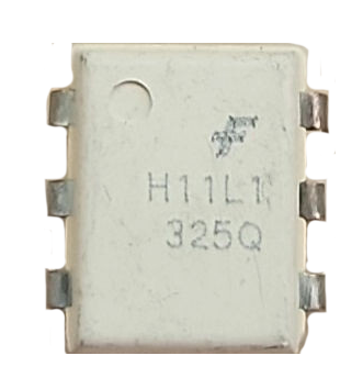
The H11L1M is an optocoupler designed to provide electrical isolation between its input and output. It consists of an infrared light-emitting diode (LED) and a phototransistor, which work together to transmit signals optically while maintaining complete electrical separation. This makes the H11L1M ideal for applications where signal integrity and isolation are critical.
Explore Projects Built with H11L1M

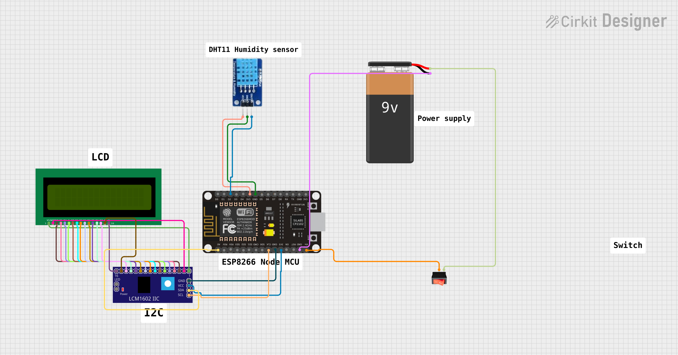
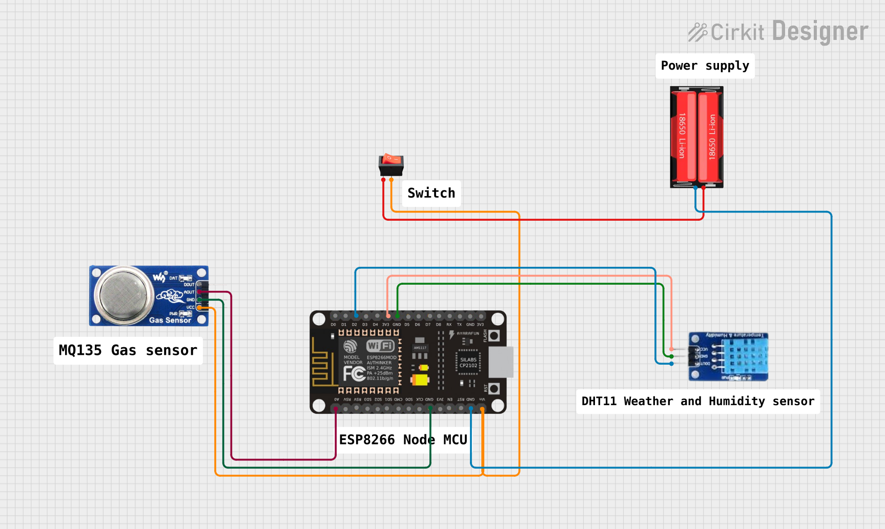
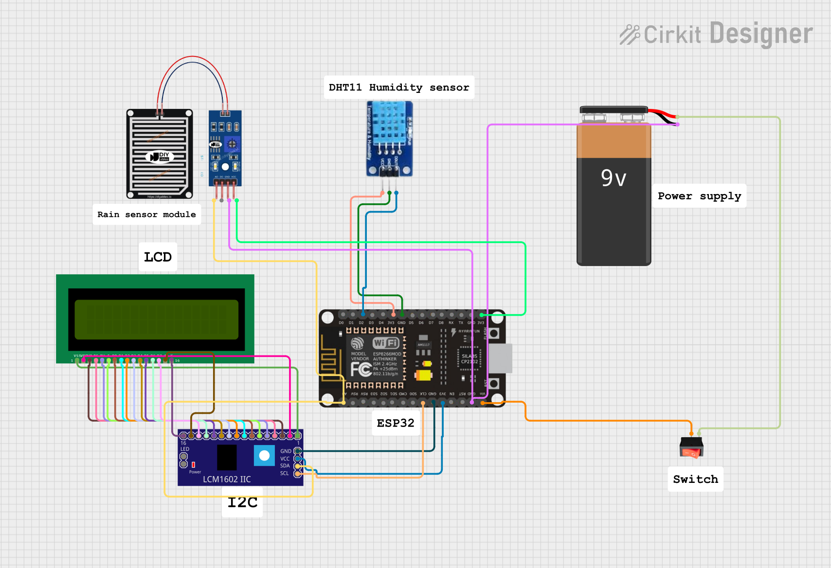
Explore Projects Built with H11L1M
Common Applications and Use Cases
- Microcontroller interfacing with high-voltage circuits
- Signal isolation in industrial control systems
- Noise suppression in sensitive electronic circuits
- Protection of low-voltage components from high-voltage transients
- Data communication between systems with different ground potentials
Technical Specifications
The H11L1M optocoupler is designed for reliable performance in a variety of applications. Below are its key technical details:
Key Specifications
| Parameter | Value |
|---|---|
| Input LED Forward Voltage | 1.2V (typical), 1.4V (maximum) |
| Input LED Forward Current | 10mA (typical), 20mA (maximum) |
| Output Voltage | 30V (maximum) |
| Output Current | 8mA (maximum) |
| Isolation Voltage | 5300 VRMS |
| Propagation Delay | 4µs (typical) |
| Operating Temperature | -55°C to +100°C |
Pin Configuration and Descriptions
The H11L1M is typically available in a 6-pin DIP (Dual Inline Package). Below is the pinout and description:
| Pin Number | Name | Description |
|---|---|---|
| 1 | Anode | Positive terminal of the input LED |
| 2 | Cathode | Negative terminal of the input LED |
| 3 | NC (No Connect) | Not connected internally; leave unconnected |
| 4 | Emitter | Emitter of the phototransistor (output side) |
| 5 | Collector | Collector of the phototransistor (output side) |
| 6 | Vcc | Supply voltage for the output phototransistor |
Usage Instructions
The H11L1M optocoupler is straightforward to use in circuits. Below are the steps and considerations for proper usage:
How to Use the H11L1M in a Circuit
Input Side (LED):
- Connect a current-limiting resistor in series with the LED (pins 1 and 2) to prevent excessive current.
Calculate the resistor value using the formula:R = (V_input - V_f) / I_f
Where:V_inputis the input voltageV_fis the forward voltage of the LED (1.2V typical)I_fis the desired forward current (e.g., 10mA)
- Connect a current-limiting resistor in series with the LED (pins 1 and 2) to prevent excessive current.
Output Side (Phototransistor):
- Connect the collector (pin 5) to the positive supply voltage (Vcc) through a pull-up resistor.
- The emitter (pin 4) is connected to ground.
- The output signal can be read at the collector (pin 5).
Power Supply:
- Ensure the supply voltage (Vcc) does not exceed the maximum rating of 30V.
Important Considerations and Best Practices
- Isolation: Ensure that the input and output sides are electrically isolated to maintain the optocoupler's functionality.
- Resistor Selection: Use appropriate resistor values to limit current and avoid damage to the LED or phototransistor.
- Temperature: Operate the H11L1M within its specified temperature range (-55°C to +100°C) to ensure reliable performance.
- Noise Suppression: For high-speed applications, consider adding a small capacitor across the output to filter noise.
Example: Connecting the H11L1M to an Arduino UNO
The H11L1M can be used to interface an Arduino UNO with an external circuit. Below is an example circuit and code:
Circuit Description
- The input LED (pins 1 and 2) is connected to an Arduino digital pin with a current-limiting resistor.
- The output phototransistor (pins 4 and 5) is connected to a pull-up resistor, and the signal is read by another Arduino digital pin.
Arduino Code
// Define pin connections
const int inputPin = 7;  // Arduino pin connected to the LED (input side)
const int outputPin = 8; // Arduino pin reading the phototransistor (output side)

void setup() {
  pinMode(inputPin, OUTPUT); // Set inputPin as output to drive the LED
  pinMode(outputPin, INPUT); // Set outputPin as input to read the signal
  Serial.begin(9600);        // Initialize serial communication for debugging
}

void loop() {
  // Turn on the LED by setting inputPin HIGH
  digitalWrite(inputPin, HIGH);
  delay(1000); // Wait for 1 second

  // Read the output signal from the phototransistor
  int outputState = digitalRead(outputPin);

  // Print the output state to the Serial Monitor
  Serial.print("Output State: ");
  Serial.println(outputState);

  // Turn off the LED by setting inputPin LOW
  digitalWrite(inputPin, LOW);
  delay(1000); // Wait for 1 second
}
Troubleshooting and FAQs
Common Issues and Solutions
No Output Signal:
- Cause: Incorrect resistor values or insufficient input current.
- Solution: Verify the current-limiting resistor value and ensure the input current is within the specified range (10-20mA).
Output Signal is Noisy:
- Cause: Electrical noise or improper grounding.
- Solution: Add a small capacitor (e.g., 0.1µF) across the output to filter noise and ensure proper grounding.
Component Overheating:
- Cause: Excessive current through the LED or phototransistor.
- Solution: Double-check resistor values and ensure the current does not exceed the maximum ratings.
Isolation Not Working:
- Cause: Input and output sides are not properly isolated.
- Solution: Ensure there is no direct electrical connection between the input and output sides.
FAQs
Q: Can the H11L1M be used for high-speed signal transmission?
A: Yes, the H11L1M has a typical propagation delay of 4µs, making it suitable for moderate-speed applications. For higher speeds, consider optocouplers designed specifically for high-speed operation.
Q: What is the maximum voltage the H11L1M can isolate?
A: The H11L1M provides an isolation voltage of up to 5300 VRMS, making it suitable for high-voltage isolation applications.
Q: Can I use the H11L1M with a 3.3V microcontroller?
A: Yes, the H11L1M can be used with a 3.3V microcontroller. Ensure the current-limiting resistor is calculated based on the 3.3V supply.
Q: Is the H11L1M suitable for AC signal isolation?
A: Yes, the H11L1M can isolate AC signals, but additional circuitry may be required to condition the signal for proper operation.