
How to Use mini voltmeter 3 wire 4-100V DC: Examples, Pinouts, and Specs
 Design with mini voltmeter 3 wire 4-100V DC in Cirkit Designer
Introduction
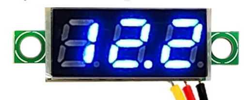
The Mini Voltmeter 3 Wire 4-100V DC is a compact and efficient device designed to measure DC voltage within a range of 4 to 100 volts. Its three-wire design ensures easy integration into a variety of electronic circuits, making it a versatile tool for hobbyists, engineers, and technicians. This voltmeter is commonly used in battery monitoring, power supply testing, and other applications where precise voltage measurement is essential.
Explore Projects Built with mini voltmeter 3 wire 4-100V DC
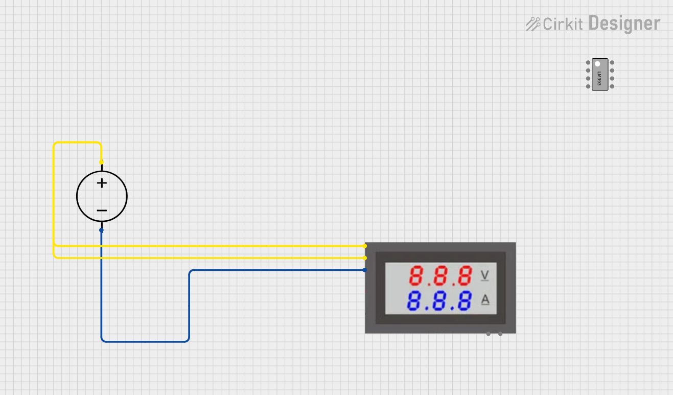 Open Project in Cirkit Designer
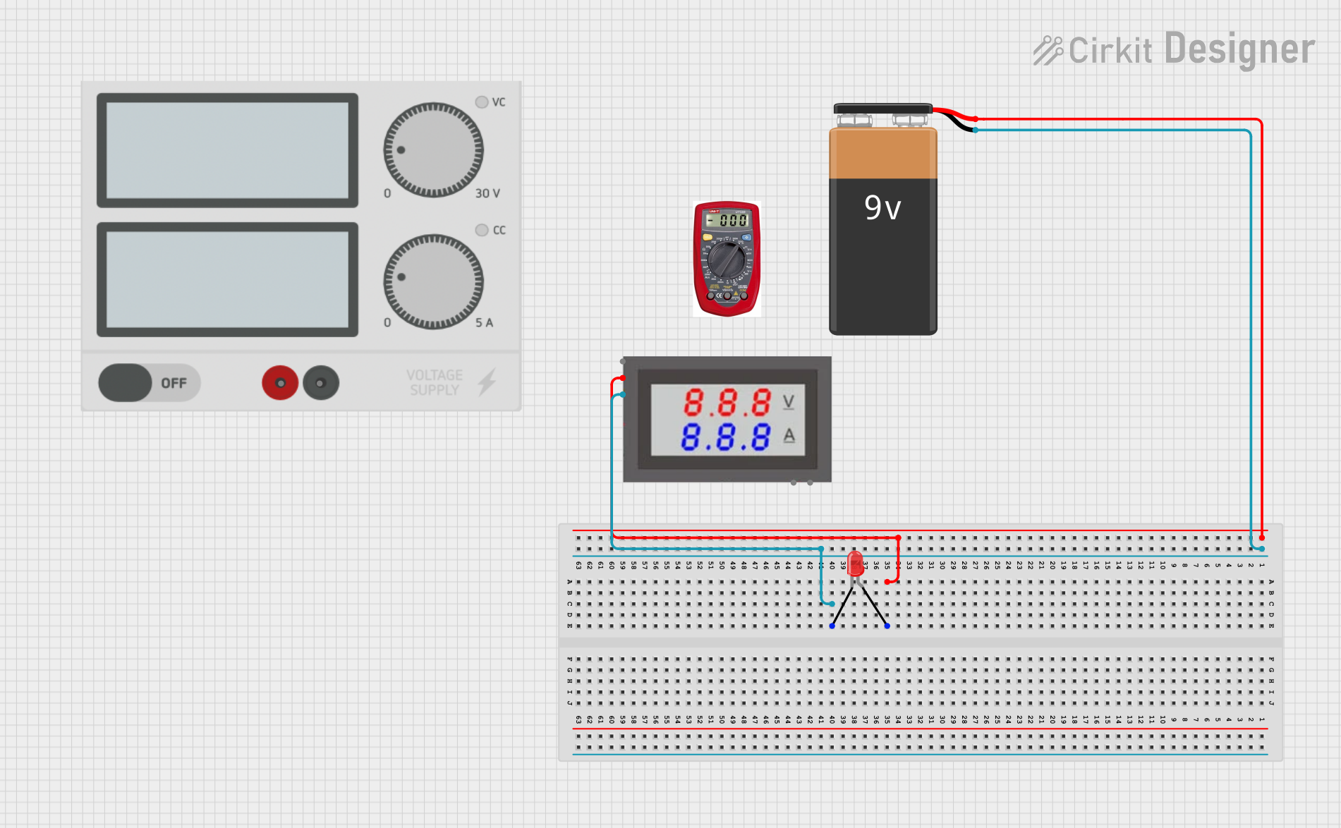 Open Project in Cirkit Designer
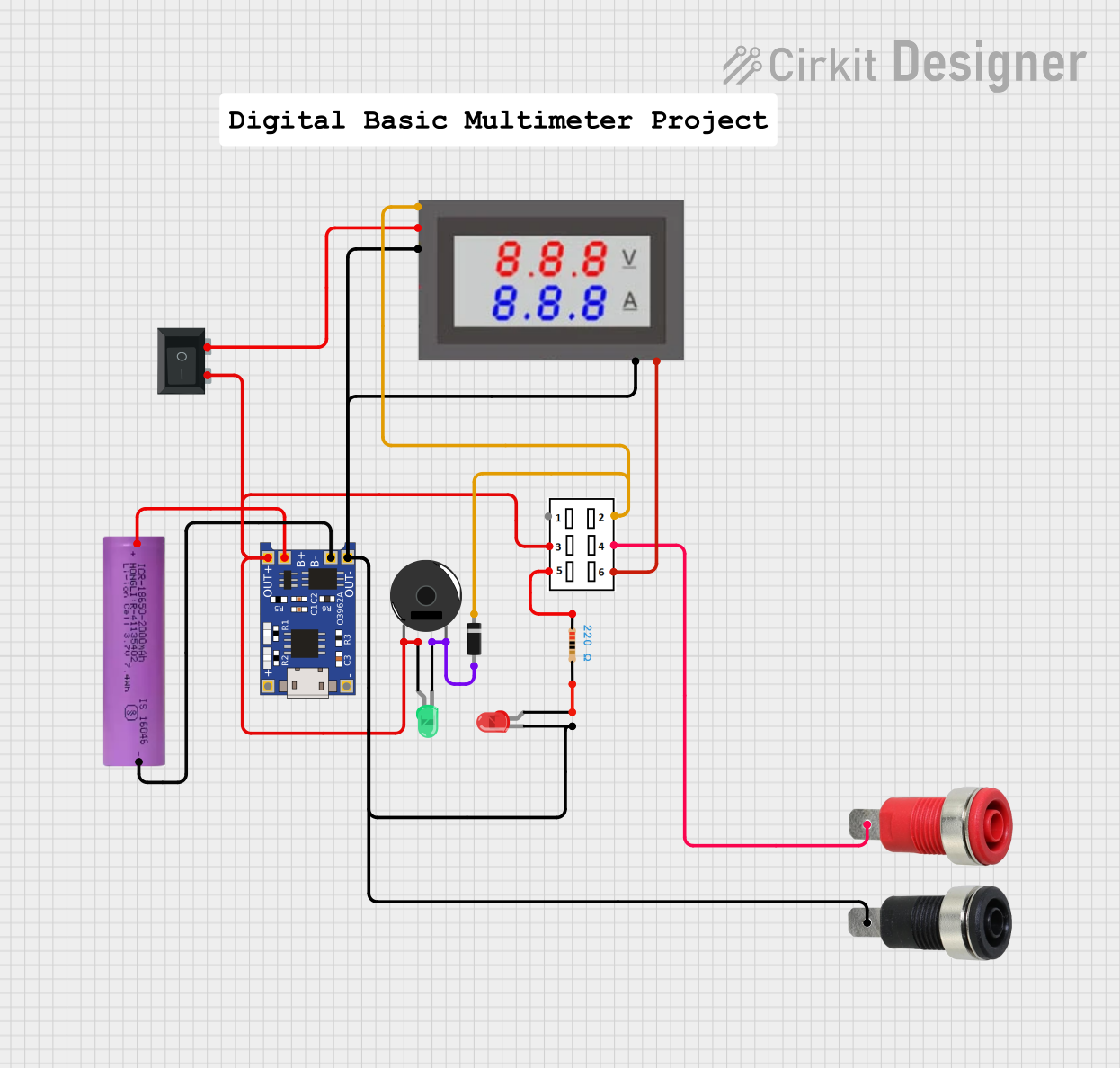 Open Project in Cirkit Designer
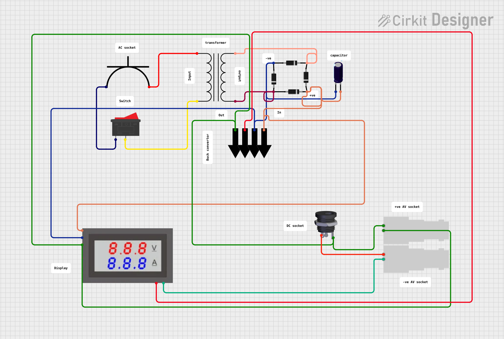 Open Project in Cirkit Designer
Explore Projects Built with mini voltmeter 3 wire 4-100V DC
Open Project in Cirkit DesignerOpen Project in Cirkit DesignerOpen Project in Cirkit DesignerOpen Project in Cirkit DesignerCommon Applications:
- Monitoring battery voltage in automotive or renewable energy systems
- Testing and troubleshooting DC power supplies
- Integration into DIY electronics projects
- Voltage monitoring in industrial control systems
Technical Specifications
Below are the key technical details of the Mini Voltmeter 3 Wire 4-100V DC:
| Parameter | Specification |
|---|---|
| Voltage Measurement Range | 4V to 100V DC |
| Operating Voltage | 4V to 30V DC |
| Display Type | 3-digit 7-segment LED display |
| Display Color | Red, Green, or Blue (varies by model) |
| Measurement Accuracy | ±1% |
| Refresh Rate | ~200ms |
| Input Impedance | >100kΩ |
| Operating Temperature | -10°C to +65°C |
| Dimensions | ~48mm x 29mm x 21mm |
| Wire Length | ~15cm |
Pin Configuration and Descriptions
The Mini Voltmeter has three wires for connection:
| Wire Color | Function | Description |
|---|---|---|
| Red | Positive Power Supply (Vcc) | Connect to a DC voltage source (4-30V) to power the voltmeter. |
| Black | Ground (GND) | Connect to the ground of the power source or circuit. |
| Yellow | Voltage Measurement Input (Vin) | Connect to the positive terminal of the voltage source to be measured (4-100V). |
Note: The red wire powers the voltmeter, while the yellow wire is used for voltage measurement. Ensure the measured voltage (Vin) is within the specified range (4-100V DC).
Usage Instructions
How to Use the Mini Voltmeter in a Circuit
Power the Voltmeter:
- Connect the red wire to a DC power source (4-30V) to supply power to the voltmeter.
- Connect the black wire to the ground of the power source.
Connect the Voltage Measurement Input:
- Attach the yellow wire to the positive terminal of the voltage source you want to measure.
- Ensure the voltage being measured is within the range of 4-100V DC.
Verify Connections:
- Double-check all connections to ensure proper polarity and avoid damage to the voltmeter.
Read the Display:
- Once powered, the voltmeter will display the measured voltage on its LED screen.
Important Considerations and Best Practices
- Power Supply Voltage: Ensure the power supply voltage (red wire) is within the range of 4-30V DC. Exceeding this range may damage the voltmeter.
- Voltage Measurement Range: Do not connect the yellow wire to a voltage source exceeding 100V DC, as this can permanently damage the device.
- Polarity: Always observe correct polarity when connecting the wires. Reversing the polarity may damage the voltmeter.
- Isolation: If the voltage source being measured shares the same ground as the power supply, ensure proper isolation to avoid ground loops or measurement errors.
- Mounting: Secure the voltmeter in a stable position to prevent accidental disconnections or damage.
Example: Using the Mini Voltmeter with an Arduino UNO
The Mini Voltmeter can be used alongside an Arduino UNO to monitor voltage in a circuit. Below is an example of how to connect and use the voltmeter:
- Connect the red wire of the voltmeter to the Arduino's 5V pin.
- Connect the black wire to the Arduino's GND pin.
- Connect the yellow wire to the positive terminal of the voltage source you want to measure.
Here is an Arduino sketch to read and display the voltage on the serial monitor:
// Arduino code to read voltage and display it on the serial monitor
const int voltagePin = A0; // Analog pin connected to the voltage divider
float voltage = 0.0;       // Variable to store the measured voltage

void setup() {
  Serial.begin(9600); // Initialize serial communication at 9600 baud
}

void loop() {
  int sensorValue = analogRead(voltagePin); // Read the analog input
  voltage = sensorValue * (5.0 / 1023.0);   // Convert to voltage (assuming 5V reference)

  // Print the voltage to the serial monitor
  Serial.print("Measured Voltage: ");
  Serial.print(voltage);
  Serial.println(" V");

  delay(500); // Wait for 500ms before the next reading
}
Note: If the voltage to be measured exceeds 5V, use a voltage divider circuit to step it down to a safe range for the Arduino's analog input.
Troubleshooting and FAQs
Common Issues and Solutions
No Display on the Voltmeter:
- Cause: The power supply voltage (red wire) is too low or disconnected.
- Solution: Ensure the red wire is connected to a DC power source within the range of 4-30V.
Incorrect Voltage Reading:
- Cause: Loose or incorrect connections, or the measured voltage is outside the specified range.
- Solution: Verify all connections and ensure the measured voltage is between 4-100V DC.
Flickering Display:
- Cause: Insufficient power supply or unstable voltage source.
- Solution: Use a stable DC power source and ensure proper connections.
Voltmeter Overheating:
- Cause: Exceeding the maximum voltage or incorrect wiring.
- Solution: Disconnect immediately and check the wiring and voltage levels.
FAQs
Q1: Can the Mini Voltmeter measure AC voltage?
A1: No, this voltmeter is designed for DC voltage measurement only. Measuring AC voltage may damage the device.
Q2: Can I power the voltmeter and measure voltage from the same source?
A2: Yes, as long as the source voltage is within the range of 4-30V DC for powering the voltmeter and 4-100V DC for measurement.
Q3: What happens if I reverse the polarity of the wires?
A3: Reversing the polarity may damage the voltmeter. Always double-check the connections before powering the device.
Q4: Can I use this voltmeter in outdoor applications?
A4: The voltmeter is not waterproof or weatherproof. Use it in a dry and controlled environment or enclose it in a protective case for outdoor use.