Cirkit Designer Logo
Cirkit Designer
Your all-in-one circuit design IDE
Home / 
Component Documentation

How to Use Qwiic Quad Relay Rev2: Examples, Pinouts, and Specs

Image of Qwiic Quad Relay Rev2
Cirkit Designer LogoDesign with Qwiic Quad Relay Rev2 in Cirkit Designer

Introduction

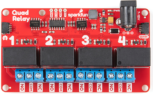
The Qwiic Quad Relay Rev2 by SparkFun is a versatile relay module designed to control high-power devices using low-power signals. It features four independent relays, each capable of switching up to 10A at 250VAC or 30VDC. The module is equipped with the Qwiic connect system, enabling seamless integration with other Qwiic-enabled devices without the need for soldering or complex wiring.

This module is ideal for applications such as:

  • Home automation (e.g., controlling lights, fans, or appliances)
  • Industrial control systems
  • Robotics and IoT projects
  • Prototyping and educational purposes

Explore Projects Built with Qwiic Quad Relay Rev2

Use Cirkit Designer to design, explore, and prototype these projects online. Some projects support real-time simulation. Click "Open Project" to start designing instantly!
ESP32-S3 Based Smart IoT Distance Sensor with Ethernet Connectivity
Image of ttt: A project utilizing Qwiic Quad Relay Rev2 in a practical application
This circuit features an ESP32-S3 microcontroller interfaced with a KY-019 Relay module, a VL53L1X time-of-flight sensor, and a W5500 Ethernet module. The ESP32-S3 controls the relay and communicates with the VL53L1X sensor via I2C, as well as with the network through the Ethernet module. An AC source is converted to DC for powering the components, and a micro USB connection is used to trigger the relay.
Cirkit Designer LogoOpen Project in Cirkit Designer
Arduino-Controlled Soundwave Generator with IR Sensor Activation and LCD Feedback
Image of Fish Attractor: A project utilizing Qwiic Quad Relay Rev2 in a practical application
This circuit features an Arduino UNO R4 WiFi microcontroller programmed to control a 4-channel relay, read from two IR sensors, and adjust a micro servo's position based on the IR sensors' input. It also generates variable frequency sound waves through a speaker using an XR2206 function generator, with the frequency adjusted by a potentiometer. An LCD I2C display is used to show the frequency and IR sensor status, and the sound's volume is controlled by a PAM8403 amplifier.
Cirkit Designer LogoOpen Project in Cirkit Designer
Wi-Fi Controlled 4-Channel Relay System with Arduino and ESP8266
Image of Wi-Fi Controlled 4-Channel Relay with Arduino and ESP8266: A project utilizing Qwiic Quad Relay Rev2 in a practical application
This circuit is a Wi-Fi controlled 4-channel relay system using an Arduino UNO and an ESP8266 module. The relays can be controlled via a web interface served by the ESP8266, and the status of each relay is displayed on a 16x4 I2C LCD. The relays are used to control four 220V AC red lights, and the Arduino communicates with the ESP8266 via serial communication.
Cirkit Designer LogoOpen Project in Cirkit Designer
Wi-Fi Controlled Relay Module with ESP8266 and MCP23017
Image of smart home: A project utilizing Qwiic Quad Relay Rev2 in a practical application
This circuit is a WiFi-enabled relay control system using an ESP8266-01 module and an MCP23017 I/O expander. The ESP8266 communicates with the MCP23017 via I2C to control an 8-channel relay module based on the state of 8 rocker switches, allowing for remote and manual control of connected devices.
Cirkit Designer LogoOpen Project in Cirkit Designer

Explore Projects Built with Qwiic Quad Relay Rev2

Use Cirkit Designer to design, explore, and prototype these projects online. Some projects support real-time simulation. Click "Open Project" to start designing instantly!
Image of ttt: A project utilizing Qwiic Quad Relay Rev2 in a practical application
ESP32-S3 Based Smart IoT Distance Sensor with Ethernet Connectivity
This circuit features an ESP32-S3 microcontroller interfaced with a KY-019 Relay module, a VL53L1X time-of-flight sensor, and a W5500 Ethernet module. The ESP32-S3 controls the relay and communicates with the VL53L1X sensor via I2C, as well as with the network through the Ethernet module. An AC source is converted to DC for powering the components, and a micro USB connection is used to trigger the relay.
Cirkit Designer LogoOpen Project in Cirkit Designer
Image of Fish Attractor: A project utilizing Qwiic Quad Relay Rev2 in a practical application
Arduino-Controlled Soundwave Generator with IR Sensor Activation and LCD Feedback
This circuit features an Arduino UNO R4 WiFi microcontroller programmed to control a 4-channel relay, read from two IR sensors, and adjust a micro servo's position based on the IR sensors' input. It also generates variable frequency sound waves through a speaker using an XR2206 function generator, with the frequency adjusted by a potentiometer. An LCD I2C display is used to show the frequency and IR sensor status, and the sound's volume is controlled by a PAM8403 amplifier.
Cirkit Designer LogoOpen Project in Cirkit Designer
Image of Wi-Fi Controlled 4-Channel Relay with Arduino and ESP8266: A project utilizing Qwiic Quad Relay Rev2 in a practical application
Wi-Fi Controlled 4-Channel Relay System with Arduino and ESP8266
This circuit is a Wi-Fi controlled 4-channel relay system using an Arduino UNO and an ESP8266 module. The relays can be controlled via a web interface served by the ESP8266, and the status of each relay is displayed on a 16x4 I2C LCD. The relays are used to control four 220V AC red lights, and the Arduino communicates with the ESP8266 via serial communication.
Cirkit Designer LogoOpen Project in Cirkit Designer
Image of smart home: A project utilizing Qwiic Quad Relay Rev2 in a practical application
Wi-Fi Controlled Relay Module with ESP8266 and MCP23017
This circuit is a WiFi-enabled relay control system using an ESP8266-01 module and an MCP23017 I/O expander. The ESP8266 communicates with the MCP23017 via I2C to control an 8-channel relay module based on the state of 8 rocker switches, allowing for remote and manual control of connected devices.
Cirkit Designer LogoOpen Project in Cirkit Designer

Technical Specifications

Below are the key technical details of the Qwiic Quad Relay Rev2:

Specification Details
Operating Voltage 3.3V to 5V
Relay Channels 4
Maximum Switching Voltage 250VAC / 30VDC
Maximum Switching Current 10A
Communication Interface I2C (via Qwiic connector)
I2C Address Range 0x6D (default) to 0x6F (configurable)
Dimensions 2.70" x 2.10" (68.6mm x 53.3mm)
Mounting Holes 4 (M3 screws)

Pin Configuration and Descriptions

The Qwiic Quad Relay Rev2 features the following connectors and pins:

Qwiic Connector

Pin Description
SDA I2C Data Line
SCL I2C Clock Line
GND Ground
3.3V Power Supply (3.3V)

Relay Terminals

Each relay has three terminals for connecting external devices:

Terminal Description
COM Common terminal for the relay
NO Normally Open terminal (connected to COM when active)
NC Normally Closed terminal (connected to COM when inactive)

Usage Instructions

Connecting the Qwiic Quad Relay Rev2

  1. Power the Module: Connect the Qwiic Quad Relay to a 3.3V or 5V power source using the Qwiic connector.
  2. I2C Communication: Use the Qwiic cable to connect the module to a microcontroller (e.g., Arduino UNO with a Qwiic Shield).
  3. Relay Connections: Connect the devices you want to control to the relay terminals (COM, NO, NC) as per your application requirements.

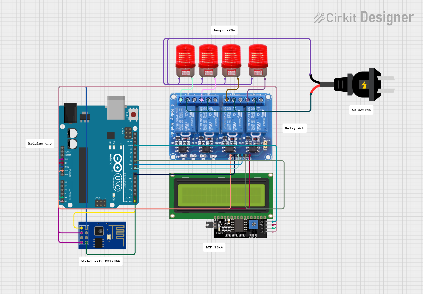
Example: Using with Arduino UNO

Below is an example of how to control the Qwiic Quad Relay Rev2 using an Arduino UNO:

Wiring

  • Attach a Qwiic Shield to the Arduino UNO.
  • Connect the Qwiic Quad Relay to the Qwiic Shield using a Qwiic cable.
  • Connect the devices to the relay terminals (e.g., a light bulb to COM and NO).

Code

#include <Wire.h>

// Default I2C address for Qwiic Quad Relay
#define RELAY_I2C_ADDRESS 0x6D

void setup() {
  Wire.begin(); // Initialize I2C communication
  Serial.begin(9600); // Start serial communication for debugging

  // Turn on Relay 1
  Wire.beginTransmission(RELAY_I2C_ADDRESS);
  Wire.write(0x01); // Command to control relays
  Wire.write(0x01); // Turn on Relay 1 (bit 0 = 1)
  Wire.endTransmission();

  Serial.println("Relay 1 is ON");
}

void loop() {
  // Add your logic here to control relays dynamically
}

Important Considerations

  • Power Supply: Ensure the power supply matches the voltage requirements of the module (3.3V or 5V).
  • Load Ratings: Do not exceed the maximum voltage (250VAC/30VDC) or current (10A) ratings of the relays.
  • Isolation: The relays provide electrical isolation between the control circuit and the high-power devices, but proper safety precautions should still be followed when working with high voltages.

Troubleshooting and FAQs

Common Issues

  1. Relays Not Switching

    • Cause: Insufficient power supply or incorrect I2C address.
    • Solution: Verify the power supply voltage and ensure the I2C address matches the default (0x6D) or the configured address.
  2. I2C Communication Failure

    • Cause: Loose Qwiic cable connection or incorrect wiring.
    • Solution: Check all Qwiic connections and ensure the SDA and SCL lines are properly connected.
  3. Relay Clicking but No Output

    • Cause: Incorrect wiring of the external device to the relay terminals.
    • Solution: Double-check the connections to COM, NO, and NC terminals.

FAQs

  1. Can I use this module with a 5V microcontroller?

    • Yes, the Qwiic Quad Relay Rev2 is compatible with both 3.3V and 5V systems.
  2. How do I change the I2C address?

    • The I2C address can be changed by modifying the address jumpers on the back of the board. Refer to the SparkFun documentation for detailed instructions.
  3. Is the module safe for high-voltage applications?

    • Yes, the relays are rated for up to 250VAC. However, always follow proper safety guidelines when working with high voltages.

By following this documentation, you can effectively integrate and use the Qwiic Quad Relay Rev2 in your projects. For additional support, refer to the official SparkFun resources.