How to Use Buck Converter LM2596: Examples, Pinouts, and Specs
Introduction
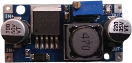
The LM2596 is a step-down (buck) voltage regulator designed to efficiently convert a higher input voltage to a lower output voltage. It is widely used in power supply applications due to its high efficiency, ease of use, and ability to handle significant current loads. The LM2596 is available in both fixed output voltage versions (e.g., 3.3V, 5V, 12V) and an adjustable version, making it versatile for various applications.
Explore Projects Built with Buck Converter LM2596


Explore Projects Built with Buck Converter LM2596
Common Applications
- Powering low-voltage devices from higher-voltage sources (e.g., 12V to 5V conversion)
- Battery-powered systems
- Embedded systems and microcontrollers
- LED drivers
- Industrial and automotive electronics
Technical Specifications
The LM2596 is a robust and reliable component with the following key specifications:
| Parameter | Value |
|---|---|
| Input Voltage Range | 4.5V to 40V |
| Output Voltage Range | 1.23V to 37V (adjustable version) |
| Output Current | Up to 3A |
| Efficiency | Up to 90% |
| Switching Frequency | 150 kHz |
| Output Voltage Tolerance | ±4% |
| Operating Temperature | -40°C to +125°C |
| Package Type | TO-220, TO-263 |
Pin Configuration and Descriptions
The LM2596 typically comes in a 5-pin package. Below is the pinout and description:
| Pin Number | Pin Name | Description |
|---|---|---|
| 1 | VIN | Input voltage (4.5V to 40V). Connect to the power source. |
| 2 | Output | Regulated output voltage. Connect to the load. |
| 3 | Ground (GND) | Ground reference for the circuit. |
| 4 | Feedback (FB) | Used to set the output voltage (adjustable version). |
| 5 | ON/OFF | Enable/disable pin. Logic high enables the regulator. |
Usage Instructions
How to Use the LM2596 in a Circuit
- Input Voltage: Connect the input voltage (VIN) to the LM2596. Ensure the input voltage is within the range of 4.5V to 40V.
- Output Voltage: For the adjustable version, use a resistor divider network connected to the Feedback (FB) pin to set the desired output voltage. For fixed versions, no external resistors are needed.
- Capacitors: Place input and output capacitors close to the LM2596 to ensure stable operation. Typical values are:
- Input capacitor: 100 µF electrolytic
- Output capacitor: 220 µF electrolytic
- Inductor: Use an appropriate inductor value (e.g., 33 µH) based on the desired output voltage and current.
- Enable Pin: If the ON/OFF pin is not used, connect it to VIN to enable the regulator.
Example Circuit
Below is a basic circuit for the adjustable version of the LM2596:
VIN (12V) ----+---- Input Capacitor (100 µF) ----+---- LM2596 (VIN)
              |                                  |
             GND                                GND

LM2596 (Output) ---- Output Capacitor (220 µF) ----+---- VOUT (5V)
              |                                  |
             GND                                GND

LM2596 (FB) ---- Resistor Divider Network ---- GND
Arduino UNO Example Code
The LM2596 can be used to power an Arduino UNO by stepping down a higher voltage (e.g., 12V) to 5V. Below is an example code to read the voltage output using the Arduino's analog input:
// Define the analog pin connected to the LM2596 output
const int voltagePin = A0;

// Function to read and calculate the output voltage
void setup() {
  Serial.begin(9600); // Initialize serial communication
}

void loop() {
  int sensorValue = analogRead(voltagePin); // Read the analog value
  float voltage = sensorValue * (5.0 / 1023.0); // Convert to voltage
  Serial.print("Output Voltage: ");
  Serial.print(voltage);
  Serial.println(" V");
  delay(1000); // Wait for 1 second before the next reading
}
Important Considerations
- Heat Dissipation: The LM2596 can get hot under high current loads. Use a heatsink if necessary.
- Input Voltage: Ensure the input voltage is at least 3V higher than the desired output voltage for proper regulation.
- Inductor Selection: Choose an inductor with a current rating higher than the maximum load current.
Troubleshooting and FAQs
Common Issues
Output Voltage is Incorrect
- Check the resistor divider network (for adjustable versions).
- Verify the input voltage is within the specified range.
Overheating
- Ensure proper heat dissipation with a heatsink or adequate ventilation.
- Check for excessive load current.
No Output Voltage
- Verify the ON/OFF pin is connected to VIN or logic high.
- Check all connections and ensure capacitors and inductors are properly placed.
Output Voltage Fluctuates
- Ensure the input and output capacitors are of the correct value and placed close to the IC.
- Check for a stable input voltage source.
FAQs
Q: Can the LM2596 be used with a battery as the input source?
A: Yes, the LM2596 can be used with batteries as long as the input voltage is within the specified range (4.5V to 40V).
Q: What is the maximum current the LM2596 can handle?
A: The LM2596 can handle up to 3A of output current, but proper heat dissipation is required at higher currents.
Q: Can I use the LM2596 to power a Raspberry Pi?
A: Yes, the LM2596 can step down a higher voltage (e.g., 12V) to 5V to power a Raspberry Pi. Ensure the output current is sufficient for the Raspberry Pi's requirements.
Q: How do I calculate the resistor values for the adjustable version?
A: Use the formula:
[
V_{OUT} = V_{REF} \times \left(1 + \frac{R_2}{R_1}\right)
]
where ( V_{REF} ) is 1.23V, ( R_1 ) is connected between FB and GND, and ( R_2 ) is connected between FB and VOUT.