Cirkit Designer Logo
Cirkit Designer
Your all-in-one circuit design IDE
Home / 
Component Documentation

How to Use PCF8575 Remote16-BIT I2C AND SMBus I/O Expander: Examples, Pinouts, and Specs
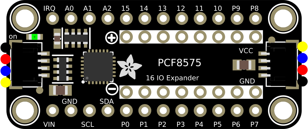

Image of PCF8575 Remote16-BIT I2C AND SMBus I/O Expander
Cirkit Designer LogoDesign with PCF8575 Remote16-BIT I2C AND SMBus I/O Expander in Cirkit Designer

Introduction

The PCF8575 is a versatile 16-bit I/O expander that communicates via the I2C or SMBus protocol. It is designed to provide additional input/output (I/O) pins for microcontrollers, enabling the expansion of GPIO capabilities in a wide range of applications. Each of the 16 GPIO pins can be individually configured as either an input or an output, making the PCF8575 suitable for tasks such as interfacing with sensors, controlling LEDs, or managing relays.

Explore Projects Built with PCF8575 Remote16-BIT I2C AND SMBus I/O Expander
Use Cirkit Designer to design, explore, and prototype these projects online. Some projects support real-time simulation. Click "Open Project" to start designing instantly!
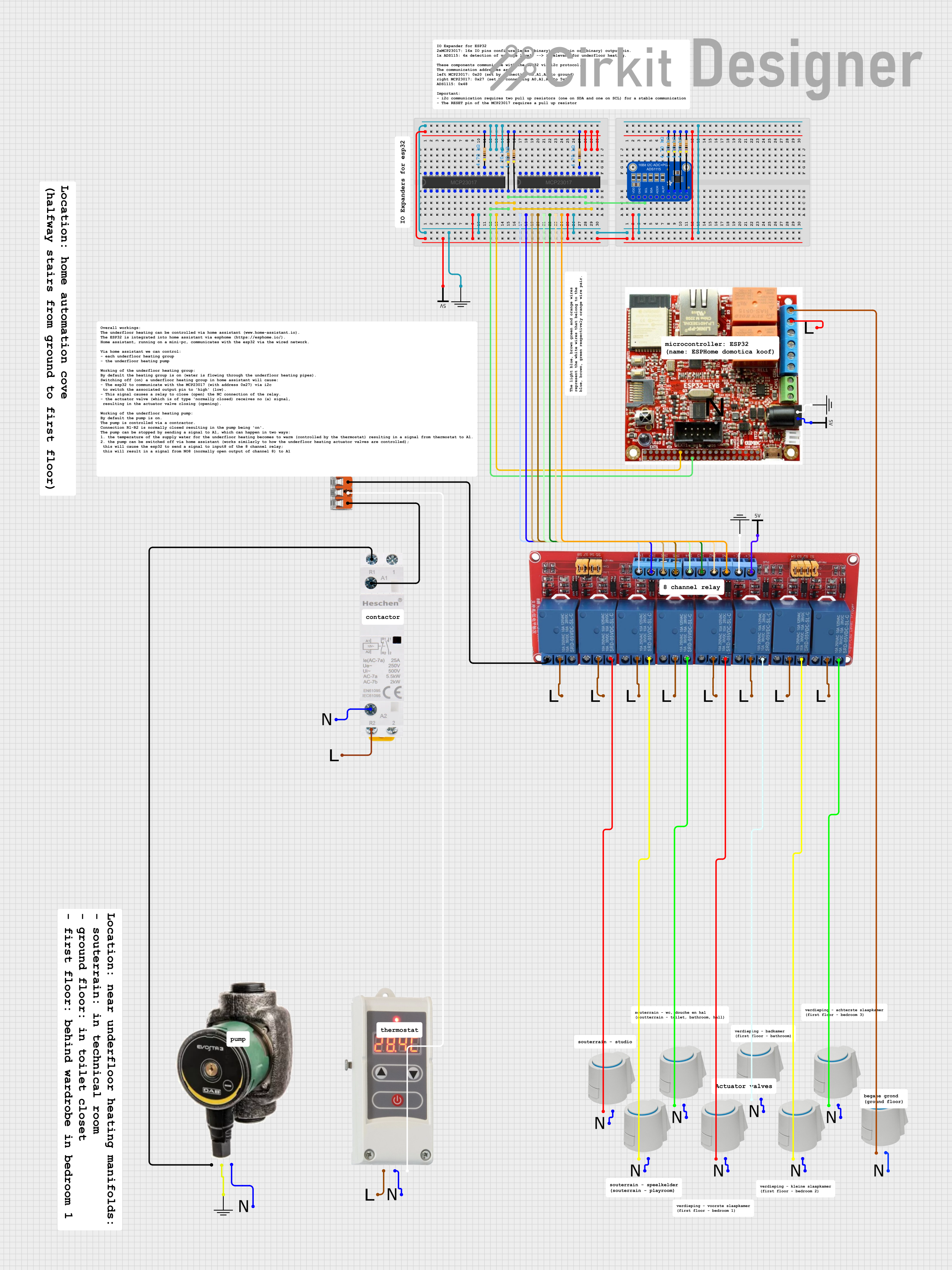
I2C-Controlled Relay Switching with ESP32 and MCP23017 for Home Automation
Image of Vloerverwarming: A project utilizing PCF8575 Remote16-BIT I2C AND SMBus I/O Expander in a practical application
This circuit appears to be a control system utilizing two MCP23017 I/O expanders interfaced with an Olimex ESP32-EVB microcontroller via I2C communication, as indicated by the SDA and SCL connections with pull-up resistors. The MCP23017 expanders control an 8-channel relay module, allowing the microcontroller to switch various loads, potentially for home automation or industrial control. Additionally, there is an Adafruit ADS1115 16-bit ADC for analog signal measurement, and several heating actuators and a thermostat are connected, suggesting temperature control functionality.
Cirkit Designer LogoOpen Project in Cirkit Designer
ESP32-Based I2C Communication Hub with Multiplexer and Expander
Image of Lights: A project utilizing PCF8575 Remote16-BIT I2C AND SMBus I/O Expander in a practical application
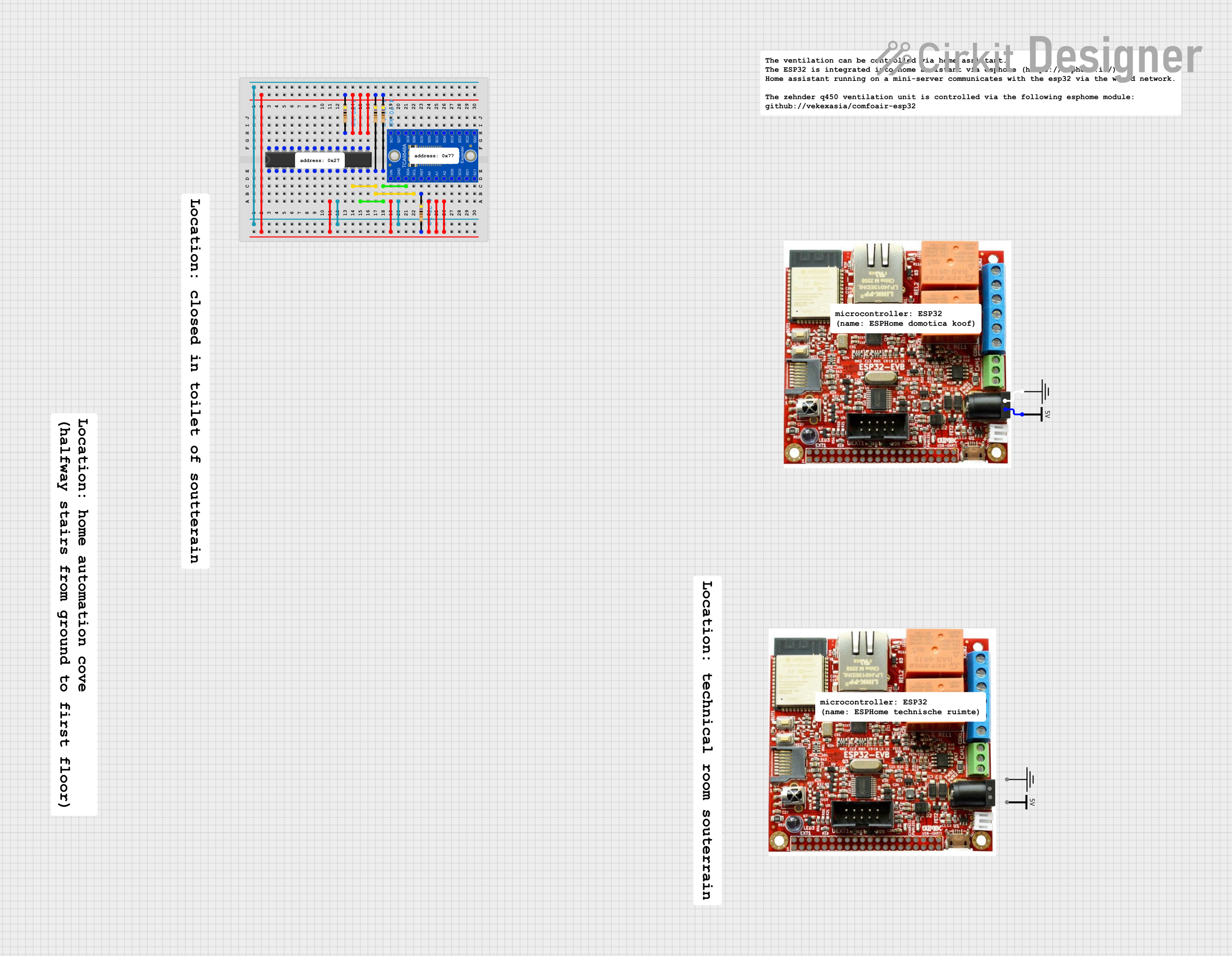
This circuit features an Olimex ESP32-EVB microcontroller unit (MCU) for processing and connectivity, interfaced with an MCP23017 I/O expander and an Adafruit TCA9548A I2C multiplexer to expand the number of I/O lines and allow multiple I2C devices to communicate with the MCU over the same bus. Pull-up resistors are connected to the I2C lines for proper bus operation, and both the MCP23017 and TCA9548A have their reset lines pulled high, likely for normal operation without external reset control.
Cirkit Designer LogoOpen Project in Cirkit Designer
MCP23017-Expanded I/O Interface with ADS1115 ADC and ESP32 Control
Image of door and window sensors: A project utilizing PCF8575 Remote16-BIT I2C AND SMBus I/O Expander in a practical application
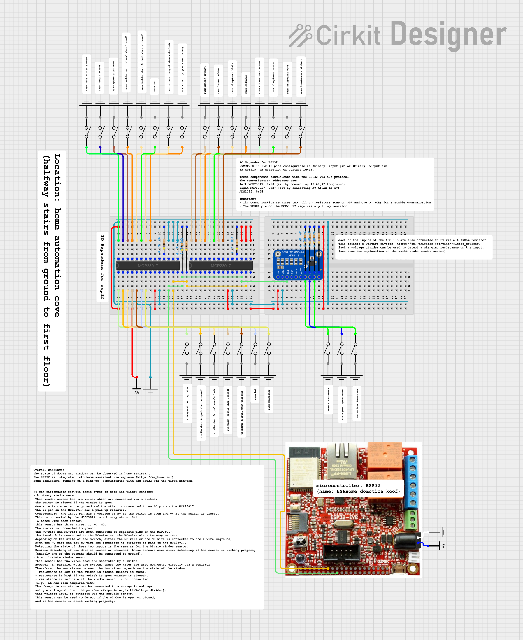
This circuit features two MCP23017 I/O expanders interfaced with multiple switches, allowing for the expansion of input capabilities. The MCP23017s are connected via I2C to an Olimex ESP32-EVB microcontroller, which likely manages the input states from the switches. Additionally, an Adafruit ADS1115 16-bit ADC is included, suggesting that some analog inputs are being monitored, with the ADC also interfaced with the ESP32 via I2C.
Cirkit Designer LogoOpen Project in Cirkit Designer
ESP32 and MCP23017-Based Smart Relay Control System with DHT22 Sensors
Image of Indoor Lounge: A project utilizing PCF8575 Remote16-BIT I2C AND SMBus I/O Expander in a practical application
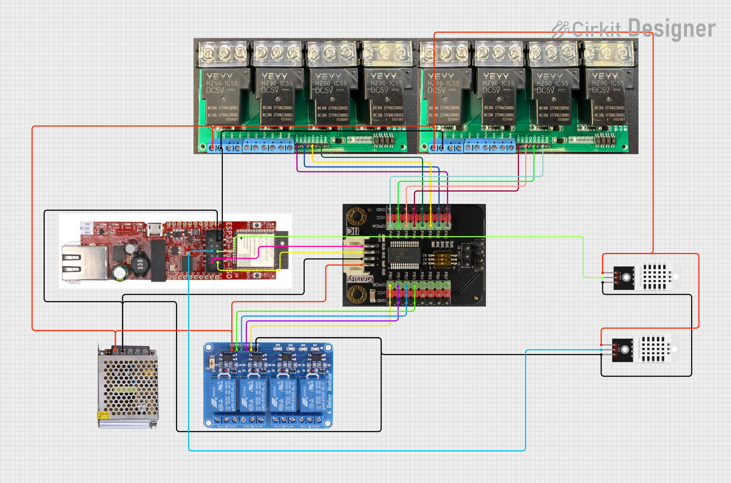
This circuit is a control system that uses an ESP32 microcontroller to manage multiple relays and read data from DHT22 temperature and humidity sensors. The DFRobot Gravity MCP23017 I2C module expands the GPIO capabilities of the ESP32, allowing it to control additional relays for switching high-power devices.
Cirkit Designer LogoOpen Project in Cirkit Designer

Explore Projects Built with PCF8575 Remote16-BIT I2C AND SMBus I/O Expander

Use Cirkit Designer to design, explore, and prototype these projects online. Some projects support real-time simulation. Click "Open Project" to start designing instantly!
Image of Vloerverwarming: A project utilizing PCF8575 Remote16-BIT I2C AND SMBus I/O Expander in a practical application
I2C-Controlled Relay Switching with ESP32 and MCP23017 for Home Automation
This circuit appears to be a control system utilizing two MCP23017 I/O expanders interfaced with an Olimex ESP32-EVB microcontroller via I2C communication, as indicated by the SDA and SCL connections with pull-up resistors. The MCP23017 expanders control an 8-channel relay module, allowing the microcontroller to switch various loads, potentially for home automation or industrial control. Additionally, there is an Adafruit ADS1115 16-bit ADC for analog signal measurement, and several heating actuators and a thermostat are connected, suggesting temperature control functionality.
Cirkit Designer LogoOpen Project in Cirkit Designer
Image of Lights: A project utilizing PCF8575 Remote16-BIT I2C AND SMBus I/O Expander in a practical application
ESP32-Based I2C Communication Hub with Multiplexer and Expander
This circuit features an Olimex ESP32-EVB microcontroller unit (MCU) for processing and connectivity, interfaced with an MCP23017 I/O expander and an Adafruit TCA9548A I2C multiplexer to expand the number of I/O lines and allow multiple I2C devices to communicate with the MCU over the same bus. Pull-up resistors are connected to the I2C lines for proper bus operation, and both the MCP23017 and TCA9548A have their reset lines pulled high, likely for normal operation without external reset control.
Cirkit Designer LogoOpen Project in Cirkit Designer
Image of door and window sensors: A project utilizing PCF8575 Remote16-BIT I2C AND SMBus I/O Expander in a practical application
MCP23017-Expanded I/O Interface with ADS1115 ADC and ESP32 Control
This circuit features two MCP23017 I/O expanders interfaced with multiple switches, allowing for the expansion of input capabilities. The MCP23017s are connected via I2C to an Olimex ESP32-EVB microcontroller, which likely manages the input states from the switches. Additionally, an Adafruit ADS1115 16-bit ADC is included, suggesting that some analog inputs are being monitored, with the ADC also interfaced with the ESP32 via I2C.
Cirkit Designer LogoOpen Project in Cirkit Designer
Image of Indoor Lounge: A project utilizing PCF8575 Remote16-BIT I2C AND SMBus I/O Expander in a practical application
ESP32 and MCP23017-Based Smart Relay Control System with DHT22 Sensors
This circuit is a control system that uses an ESP32 microcontroller to manage multiple relays and read data from DHT22 temperature and humidity sensors. The DFRobot Gravity MCP23017 I2C module expands the GPIO capabilities of the ESP32, allowing it to control additional relays for switching high-power devices.
Cirkit Designer LogoOpen Project in Cirkit Designer

Common Applications

  • Expanding GPIO pins for microcontrollers like Arduino, Raspberry Pi, or ESP32
  • Driving LEDs, relays, or other output devices
  • Reading multiple switches or sensors
  • Industrial automation and control systems
  • Home automation projects

Technical Specifications

The following table outlines the key technical details of the PCF8575:

Parameter Value
Operating Voltage 2.5V to 5.5V
Communication Protocol I2C or SMBus
I2C Address Range 0x20 to 0x27 (configurable)
GPIO Pins 16 (individually configurable)
Maximum Sink Current (per pin) 25 mA
Maximum Source Current (per pin) 10 mA
Operating Temperature Range -40°C to +85°C
Package Types SOIC-24, TSSOP-24, SSOP-24

Pin Configuration

The PCF8575 has 24 pins, with the following configuration:

Pin Number Pin Name Description
1-8 P0.0 - P0.7 GPIO pins (lower byte)
9 VSS Ground
10-17 P1.0 - P1.7 GPIO pins (upper byte)
18 INT Interrupt output (active low)
19 A0 I2C address selection bit 0
20 A1 I2C address selection bit 1
21 A2 I2C address selection bit 2
22 SCL I2C clock line
23 SDA I2C data line
24 VDD Power supply (2.5V to 5.5V)

Usage Instructions

Connecting the PCF8575 to a Microcontroller

  1. Power Supply: Connect the VDD pin to a 3.3V or 5V power source, and the VSS pin to ground.
  2. I2C Communication: Connect the SDA and SCL pins to the corresponding I2C pins on your microcontroller. Use pull-up resistors (typically 4.7kΩ) on both SDA and SCL lines.
  3. Address Configuration: Set the I2C address by connecting the A0, A1, and A2 pins to either VDD (logic high) or VSS (logic low). This allows up to 8 devices to share the same I2C bus.
  4. GPIO Pins: Connect the GPIO pins (P0.0 to P1.7) to your desired input or output devices.

Example Code for Arduino UNO

The following example demonstrates how to use the PCF8575 with an Arduino UNO to toggle an LED connected to one of the GPIO pins.

#include <Wire.h>
#include <PCF8575.h> // Include the PCF8575 library

PCF8575 expander(0x20); // Initialize the PCF8575 with I2C address 0x20

void setup() {
  Wire.begin(); // Initialize I2C communication
  expander.begin(); // Start the PCF8575
  expander.pinMode(P0, OUTPUT); // Set pin P0 as an output
}

void loop() {
  expander.digitalWrite(P0, HIGH); // Turn on the LED connected to P0
  delay(1000); // Wait for 1 second
  expander.digitalWrite(P0, LOW); // Turn off the LED
  delay(1000); // Wait for 1 second
}

Best Practices

  • Use pull-up resistors on the SDA and SCL lines to ensure reliable I2C communication.
  • Avoid exceeding the maximum current ratings for the GPIO pins to prevent damage.
  • Use decoupling capacitors (e.g., 0.1µF) near the VDD pin to stabilize the power supply.

Troubleshooting and FAQs

Common Issues

  1. Device Not Responding on I2C Bus

    • Cause: Incorrect I2C address or wiring.
    • Solution: Verify the address configuration (A0, A1, A2 pins) and check the connections for SDA and SCL.
  2. GPIO Pins Not Functioning as Expected

    • Cause: Incorrect pin mode configuration.
    • Solution: Ensure that each pin is properly configured as an input or output using the appropriate library functions.
  3. Interrupt Pin Not Triggering

    • Cause: Interrupts not enabled or misconfigured.
    • Solution: Check the datasheet for interrupt configuration details and ensure the INT pin is connected to the microcontroller.

FAQs

Q: Can the PCF8575 handle 5V logic levels?
A: Yes, the PCF8575 supports operating voltages from 2.5V to 5.5V, making it compatible with both 3.3V and 5V systems.

Q: How many PCF8575 devices can I connect to a single I2C bus?
A: Up to 8 devices can be connected by configuring the A0, A1, and A2 address pins.

Q: Can I use the PCF8575 for PWM output?
A: The PCF8575 does not natively support PWM. However, you can simulate PWM by toggling the GPIO pins in software.

Q: What is the maximum I2C clock speed supported?
A: The PCF8575 supports I2C clock speeds up to 400kHz (Fast Mode).