Cirkit Designer Logo
Cirkit Designer
Your all-in-one circuit design IDE
Home / 
Component Documentation

How to Use Arduino MKR Wifi 1010: Examples, Pinouts, and Specs

Image of Arduino MKR Wifi 1010
Cirkit Designer LogoDesign with Arduino MKR Wifi 1010 in Cirkit Designer

Introduction

The Arduino MKR WiFi 1010 is a compact microcontroller board designed for Internet of Things (IoT) applications. Manufactured by Arduino, this board combines the power of the SAMD21 Cortex-M0+ 32-bit ARM processor with built-in Wi-Fi capabilities, making it ideal for wireless communication and IoT projects. It also features a battery connector for portable applications and a variety of I/O pins for connecting sensors, actuators, and other peripherals.

Explore Projects Built with Arduino MKR Wifi 1010

Use Cirkit Designer to design, explore, and prototype these projects online. Some projects support real-time simulation. Click "Open Project" to start designing instantly!
Arduino MKR WiFi 1010 Basic Power Supply with Voltage Divider
Image of voltqge divider: A project utilizing Arduino MKR Wifi 1010 in a practical application
This circuit features an Arduino MKR WiFi 1010 powered by a 4xAA battery holder, with the battery's positive terminal connected to the Arduino's VIN pin and the negative terminal to GND. Two 100k Ohm resistors are connected in series between the Arduino's A0 analog input and VCC, with their midpoint also tied to GND, forming a voltage divider that could be used for sensing or reference voltage purposes.
Cirkit Designer LogoOpen Project in Cirkit Designer
Arduino MKR WiFi 1010 Controlled Relay Switching Circuit
Image of Receptor lorawan: A project utilizing Arduino MKR Wifi 1010 in a practical application
This circuit consists of an Arduino MKR WiFi 1010 microcontroller connected to a 5V relay. The Arduino is programmed to receive LoRa wireless communication signals and toggle the relay based on the received data, which controls the connection between the relay's Common terminal and either the Normally Open or Normally Closed terminal. The relay's activation is dependent on the specific message received ('button pressed'), which is intended to switch a connected external load on or off.
Cirkit Designer LogoOpen Project in Cirkit Designer
Arduino MKR WiFi 1010 Environmental Monitoring Station with Multiple Sensors
Image of idojaras_allomas: A project utilizing Arduino MKR Wifi 1010 in a practical application
This circuit is designed around an Arduino MKR WiFi 1010 microcontroller and includes a variety of sensors: a water level sensor, an MQ-2 gas sensor, a TEMT6000 ambient light sensor, a steam sensor, a DHT11 temperature and humidity sensor, and a rotary encoder. The sensors are powered by the 5V output from the Arduino and their ground pins are connected to the Arduino's ground. The signal outputs from the sensors are connected to various analog and digital input pins on the Arduino, enabling it to monitor environmental conditions such as gas presence, light levels, temperature, humidity, water level, and user input through the rotary encoder.
Cirkit Designer LogoOpen Project in Cirkit Designer
Arduino MKR WiFi 1010 LoRa-Enabled Pushbutton Message Sender
Image of Emisor LORAWAN: A project utilizing Arduino MKR Wifi 1010 in a practical application
This circuit features an Arduino MKR WiFi 1010 connected to a pushbutton. When the button is pressed, the Arduino detects the input and sends a 'button pressed' message using LoRa communication. The purpose of this circuit is to wirelessly transmit a signal upon a button press, potentially for remote control or notification purposes.
Cirkit Designer LogoOpen Project in Cirkit Designer

Explore Projects Built with Arduino MKR Wifi 1010

Use Cirkit Designer to design, explore, and prototype these projects online. Some projects support real-time simulation. Click "Open Project" to start designing instantly!
Image of voltqge divider: A project utilizing Arduino MKR Wifi 1010 in a practical application
Arduino MKR WiFi 1010 Basic Power Supply with Voltage Divider
This circuit features an Arduino MKR WiFi 1010 powered by a 4xAA battery holder, with the battery's positive terminal connected to the Arduino's VIN pin and the negative terminal to GND. Two 100k Ohm resistors are connected in series between the Arduino's A0 analog input and VCC, with their midpoint also tied to GND, forming a voltage divider that could be used for sensing or reference voltage purposes.
Cirkit Designer LogoOpen Project in Cirkit Designer
Image of Receptor lorawan: A project utilizing Arduino MKR Wifi 1010 in a practical application
Arduino MKR WiFi 1010 Controlled Relay Switching Circuit
This circuit consists of an Arduino MKR WiFi 1010 microcontroller connected to a 5V relay. The Arduino is programmed to receive LoRa wireless communication signals and toggle the relay based on the received data, which controls the connection between the relay's Common terminal and either the Normally Open or Normally Closed terminal. The relay's activation is dependent on the specific message received ('button pressed'), which is intended to switch a connected external load on or off.
Cirkit Designer LogoOpen Project in Cirkit Designer
Image of idojaras_allomas: A project utilizing Arduino MKR Wifi 1010 in a practical application
Arduino MKR WiFi 1010 Environmental Monitoring Station with Multiple Sensors
This circuit is designed around an Arduino MKR WiFi 1010 microcontroller and includes a variety of sensors: a water level sensor, an MQ-2 gas sensor, a TEMT6000 ambient light sensor, a steam sensor, a DHT11 temperature and humidity sensor, and a rotary encoder. The sensors are powered by the 5V output from the Arduino and their ground pins are connected to the Arduino's ground. The signal outputs from the sensors are connected to various analog and digital input pins on the Arduino, enabling it to monitor environmental conditions such as gas presence, light levels, temperature, humidity, water level, and user input through the rotary encoder.
Cirkit Designer LogoOpen Project in Cirkit Designer
Image of Emisor LORAWAN: A project utilizing Arduino MKR Wifi 1010 in a practical application
Arduino MKR WiFi 1010 LoRa-Enabled Pushbutton Message Sender
This circuit features an Arduino MKR WiFi 1010 connected to a pushbutton. When the button is pressed, the Arduino detects the input and sends a 'button pressed' message using LoRa communication. The purpose of this circuit is to wirelessly transmit a signal upon a button press, potentially for remote control or notification purposes.
Cirkit Designer LogoOpen Project in Cirkit Designer

Common Applications and Use Cases

  • IoT devices and smart home automation
  • Wireless sensor networks
  • Remote monitoring and control systems
  • Prototyping Wi-Fi-enabled devices
  • Educational projects and workshops

Technical Specifications

Key Technical Details

  • Microcontroller: SAMD21 Cortex-M0+ 32-bit ARM processor
  • Wi-Fi Module: u-blox NINA-W102 (802.11 b/g/n)
  • Operating Voltage: 3.3V
  • Input Voltage (VIN): 5V (via USB) or 3.7V (via Li-Po battery)
  • Digital I/O Pins: 8 (of which 4 support PWM)
  • Analog Input Pins: 7 (12-bit ADC)
  • Analog Output Pins: 1 (10-bit DAC)
  • Flash Memory: 256 KB
  • SRAM: 32 KB
  • Clock Speed: 48 MHz
  • Connectivity: Wi-Fi, UART, SPI, I2C
  • Dimensions: 61.5 mm x 25 mm
  • Weight: 32 g

Pin Configuration and Descriptions

The Arduino MKR WiFi 1010 has a total of 22 pins, including digital, analog, power, and communication pins. Below is a detailed pinout description:

Digital and Analog Pins

Pin Type Description
D0-D7 Digital I/O General-purpose digital pins. D0 and D1 are also used for UART communication.
A0-A6 Analog Input 12-bit ADC pins for reading analog signals.
DAC0 Analog Output 10-bit DAC pin for generating analog signals.

Power Pins

Pin Type Description
VIN Power Input Input voltage (5V via USB or 3.7V via Li-Po battery).
3.3V Power Output Regulated 3.3V output for powering external components.
GND Ground Common ground for the circuit.

Communication Pins

Pin Type Description
TX/RX UART Serial communication pins (D0 and D1).
SCL/SDA I2C Clock and data lines for I2C communication.
MOSI SPI Master Out Slave In pin for SPI communication.
MISO SPI Master In Slave Out pin for SPI communication.
SCK SPI Clock pin for SPI communication.

Usage Instructions

How to Use the Component in a Circuit
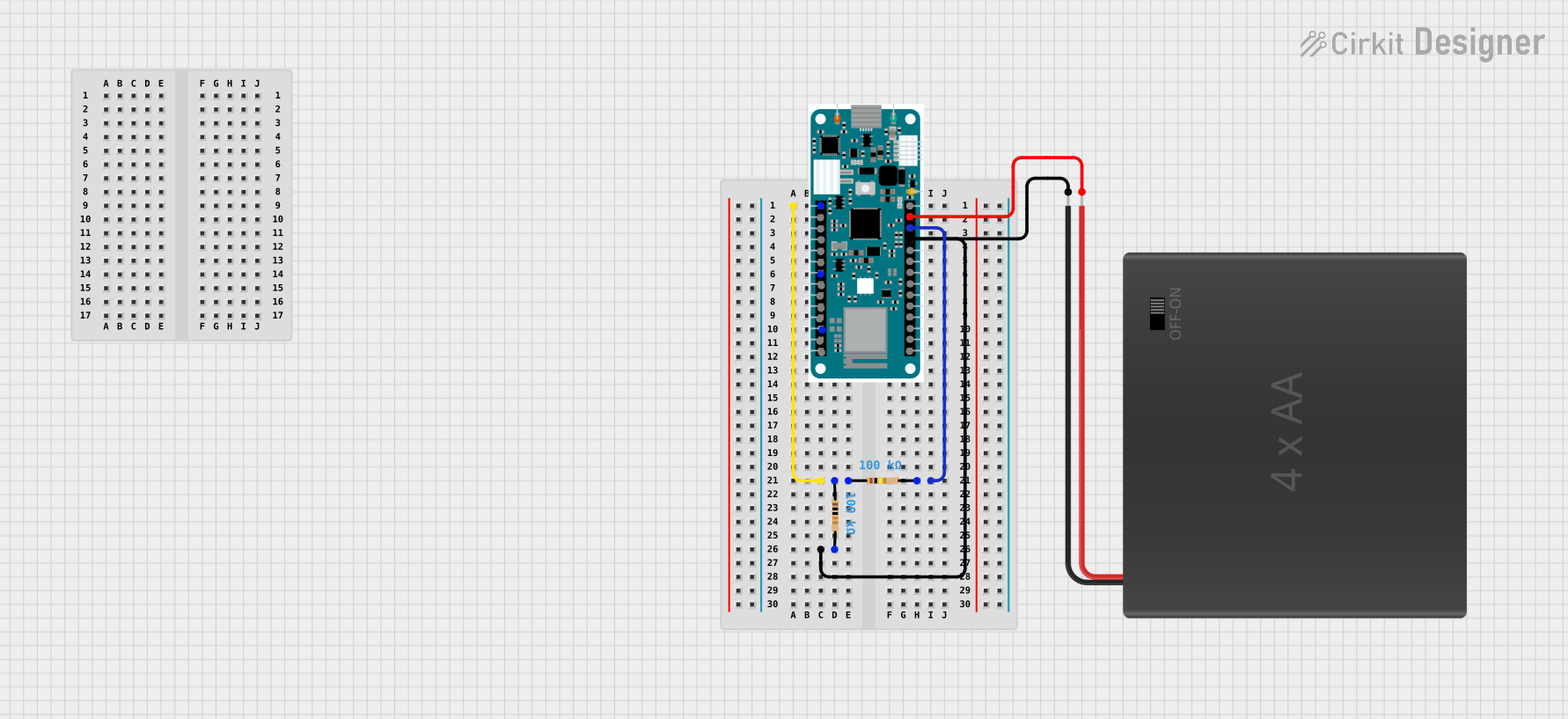
  1. Powering the Board:

    • Connect the board to a computer via a USB cable for development and power.
    • Alternatively, use a 3.7V Li-Po battery for portable applications.
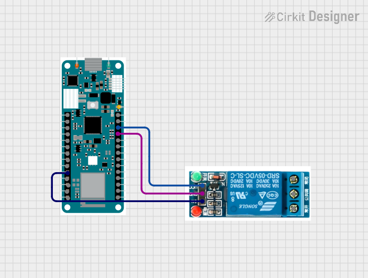
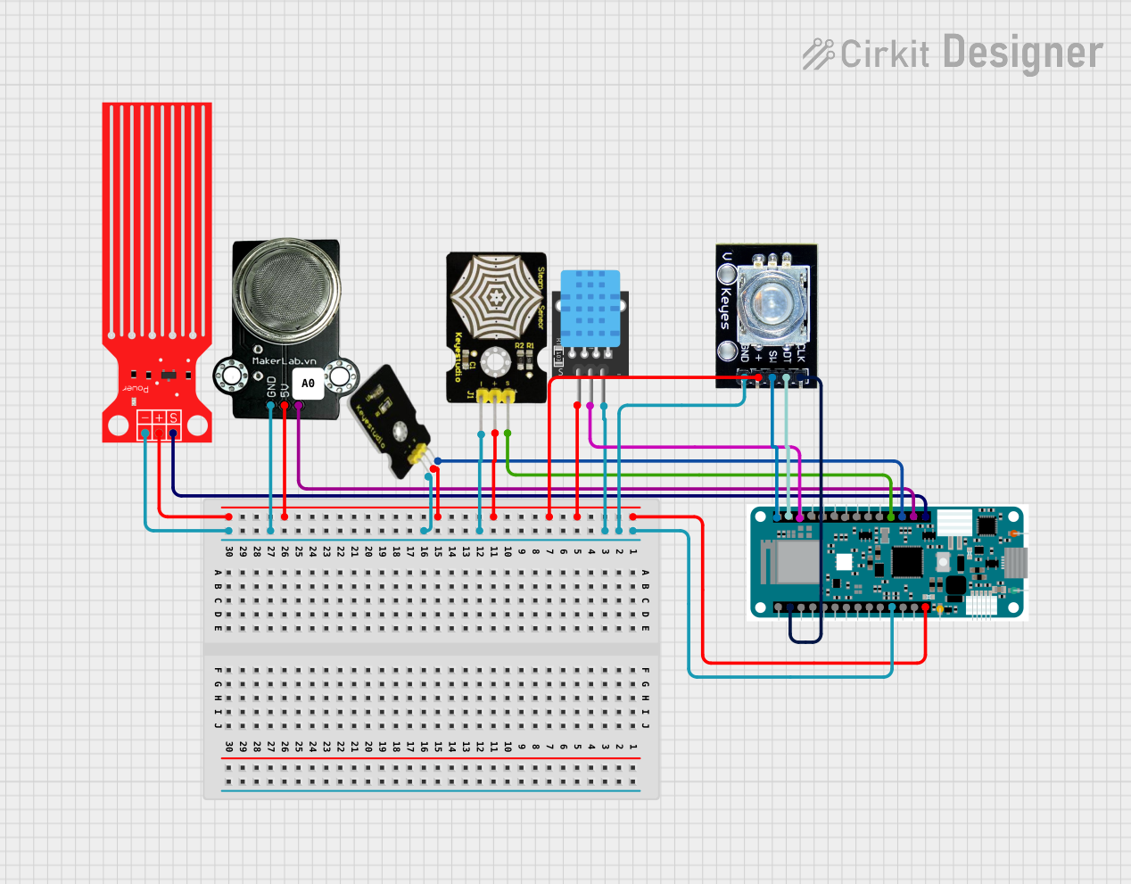
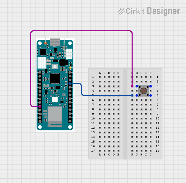
  2. Connecting Sensors and Actuators:

    • Use the digital pins (D0-D7) for digital sensors or actuators.
    • Use the analog pins (A0-A6) for analog sensors.
  3. Programming the Board:

    • Install the Arduino IDE and add the "Arduino SAMD Boards" package via the Board Manager.
    • Select "Arduino MKR WiFi 1010" as the board in the Tools menu.
    • Write and upload your code to the board using the USB connection.
  4. Wi-Fi Configuration:

    • Use the WiFiNINA library to connect the board to a Wi-Fi network.
    • Ensure the u-blox NINA-W102 module firmware is up to date using the Firmware Updater tool in the Arduino IDE.

Important Considerations and Best Practices

  • Voltage Levels: The board operates at 3.3V. Avoid applying 5V to the I/O pins to prevent damage.
  • Battery Usage: When using a Li-Po battery, ensure it is properly connected to the JST connector.
  • Wi-Fi Signal Strength: Place the board in an area with good Wi-Fi signal strength for reliable communication.
  • Firmware Updates: Regularly update the Wi-Fi module firmware for compatibility and security improvements.

Example Code: Connecting to Wi-Fi

Below is an example sketch to connect the Arduino MKR WiFi 1010 to a Wi-Fi network:

#include <WiFiNINA.h>

// Replace with your network credentials
const char* ssid = "Your_SSID";       // Your Wi-Fi network name
const char* password = "Your_Password"; // Your Wi-Fi network password

void setup() {
  Serial.begin(9600); // Initialize serial communication
  while (!Serial);    // Wait for the serial monitor to open

  Serial.print("Connecting to Wi-Fi...");
  int status = WiFi.begin(ssid, password); // Connect to Wi-Fi

  if (status != WL_CONNECTED) {
    Serial.println("Failed to connect to Wi-Fi");
    while (true); // Halt execution if connection fails
  }

  Serial.println("Connected to Wi-Fi!");
  Serial.print("IP Address: ");
  Serial.println(WiFi.localIP()); // Print the board's IP address
}

void loop() {
  // Add your main code here
}

Troubleshooting and FAQs

Common Issues and Solutions

  1. The board is not recognized by the computer:

    • Ensure the USB cable is properly connected and is a data cable (not power-only).
    • Check if the correct board and port are selected in the Arduino IDE.
  2. Wi-Fi connection fails:

    • Verify the SSID and password are correct.
    • Ensure the Wi-Fi network is within range and supports 2.4 GHz (not 5 GHz).
  3. Firmware update errors:

    • Use the Firmware Updater tool in the Arduino IDE to update the Wi-Fi module firmware.
    • Ensure the board is connected to the computer during the update process.
  4. Overheating or instability:

    • Avoid exceeding the maximum current draw of the board.
    • Use proper heat dissipation techniques if the board is used in high-power applications.

FAQs

  • Can I use the board with 5V sensors?
    No, the board operates at 3.3V. Use a level shifter to interface with 5V sensors.

  • What is the maximum range of the Wi-Fi module?
    The range depends on the environment but is typically up to 100 meters in open spaces.

  • Can I power the board with a power bank?
    Yes, you can use a power bank with a USB output to power the board.

  • Is the board compatible with Arduino shields?
    No, the MKR form factor is different from the standard Arduino Uno shields. Use MKR-compatible shields.