
How to Use Transformer 240V - Dual Secondary 12-15V: Examples, Pinouts, and Specs
 Design with Transformer 240V - Dual Secondary 12-15V in Cirkit Designer
Introduction
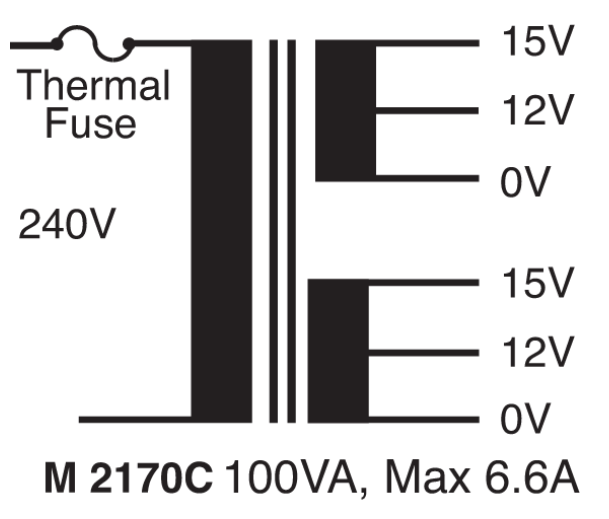
The PowerTran M 2170C is a step-down transformer designed to convert a 240V AC input into two isolated secondary outputs of 12-15V AC. This transformer is ideal for applications requiring low-voltage AC power, such as power supplies, audio amplifiers, and low-voltage lighting systems. Its dual secondary windings provide flexibility for series or parallel configurations, enabling a range of output voltage and current options.
Explore Projects Built with Transformer 240V - Dual Secondary 12-15V
 Open Project in Cirkit Designer
 Open Project in Cirkit Designer
 Open Project in Cirkit Designer
 Open Project in Cirkit Designer
Explore Projects Built with Transformer 240V - Dual Secondary 12-15V
Open Project in Cirkit DesignerOpen Project in Cirkit DesignerOpen Project in Cirkit DesignerOpen Project in Cirkit DesignerCommon Applications
- Power supply circuits for electronic devices
- Audio equipment and amplifiers
- Low-voltage lighting systems
- Battery charging circuits
- General-purpose AC voltage step-down applications
Technical Specifications
Electrical Characteristics
| Parameter | Value |
|---|---|
| Manufacturer | PowerTran |
| Part Number | M 2170C |
| Input Voltage | 240V AC |
| Output Voltage (Secondary) | Dual 12-15V AC |
| Output Current (Max) | 1.5A per secondary winding |
| Frequency | 50/60 Hz |
| Power Rating | 36VA |
| Insulation Class | Class B (130°C max) |
Pin Configuration and Descriptions
The transformer has six terminals: two for the primary winding and four for the dual secondary windings.
Terminal Configuration
| Terminal Number | Description |
|---|---|
| 1, 2 | Primary winding (240V AC input) |
| 3, 4 | Secondary winding 1 (12-15V AC) |
| 5, 6 | Secondary winding 2 (12-15V AC) |
Wiring Notes
- The secondary windings can be connected in series to double the voltage (24-30V AC) or in parallel to double the current capacity (up to 3A).
- Ensure proper insulation and secure connections to avoid short circuits or electrical hazards.
Usage Instructions
How to Use the Transformer in a Circuit
Primary Connection:
- Connect terminals 1 and 2 to a 240V AC mains supply. Use a fuse or circuit breaker rated for the transformer’s input current to protect the circuit.
- Ensure proper grounding for safety.
Secondary Connection:
- For a single 12-15V AC output, use one of the secondary windings (e.g., terminals 3 and 4).
- For higher voltage (24-30V AC), connect the secondary windings in series:
- Connect terminal 4 to terminal 5.
- Use terminals 3 and 6 as the output.
- For higher current (up to 3A), connect the secondary windings in parallel:
- Connect terminal 3 to terminal 5 and terminal 4 to terminal 6.
- Use terminals 3 and 4 (or 5 and 6) as the output.
Rectification and Regulation:
- To convert the AC output to DC, use a bridge rectifier circuit followed by a smoothing capacitor and a voltage regulator if required.
Important Considerations
- Safety: Always handle the transformer with care when working with high voltages. Ensure the primary side is properly insulated and grounded.
- Load Matching: Do not exceed the maximum current rating of 1.5A per secondary winding (or 3A in parallel configuration).
- Heat Dissipation: Transformers can generate heat during operation. Ensure adequate ventilation or heat sinking if used in an enclosed space.
- Testing: Use a multimeter to verify the output voltage before connecting the transformer to your circuit.
Example: Using with an Arduino UNO
To power an Arduino UNO, the transformer’s AC output must first be converted to DC. Below is an example circuit and code for using the transformer with an Arduino UNO:
Circuit Steps
- Connect the transformer’s secondary winding to a bridge rectifier.
- Add a smoothing capacitor (e.g., 1000µF, 25V) to the rectifier output.
- Use a 7805 voltage regulator to step down the rectified voltage to 5V DC.
- Connect the 5V DC output to the Arduino UNO’s 5V and GND pins.
Arduino Code Example
// Example code to blink an LED connected to pin 13
// Ensure the Arduino is powered via the transformer circuit

void setup() {
  pinMode(13, OUTPUT); // Set pin 13 as an output
}

void loop() {
  digitalWrite(13, HIGH); // Turn the LED on
  delay(1000);            // Wait for 1 second
  digitalWrite(13, LOW);  // Turn the LED off
  delay(1000);            // Wait for 1 second
}
Troubleshooting and FAQs
Common Issues
No Output Voltage:
- Check the primary connections to ensure the transformer is receiving 240V AC.
- Verify that the fuse or circuit breaker is not blown.
- Inspect the secondary connections for loose or broken wires.
Overheating:
- Ensure the transformer is not overloaded. Check the current draw of the connected load.
- Verify that the transformer is installed in a well-ventilated area.
Incorrect Output Voltage:
- Measure the output voltage with a multimeter. If the voltage is too low, check for excessive load or incorrect wiring.
- If using the windings in series or parallel, ensure the connections are correct.
Humming Noise:
- A slight humming noise is normal due to magnetostriction. However, excessive noise may indicate loose mounting or overloading.
FAQs
Q: Can I use this transformer for DC applications?
A: The transformer itself provides AC output. To use it for DC applications, you need to add a rectifier, smoothing capacitor, and voltage regulator.
Q: What happens if I connect the secondary windings incorrectly?
A: Incorrect wiring (e.g., wrong polarity in series or parallel connections) can result in no output or damage to the transformer. Double-check the wiring before powering the circuit.
Q: Can I use this transformer with a 120V AC input?
A: No, this transformer is designed specifically for 240V AC input. Using it with 120V AC will result in reduced output voltage.
Q: Is the transformer suitable for outdoor use?
A: No, the transformer is not weatherproof. It should be used in a dry, indoor environment.
This concludes the documentation for the PowerTran M 2170C Transformer. Always follow safety guidelines and manufacturer recommendations when using this component.