Cirkit Designer Logo
Cirkit Designer
Your all-in-one circuit design IDE
Home / 
Component Documentation

How to Use ESP32-S3-DevKit-C: Examples, Pinouts, and Specs

Image of ESP32-S3-DevKit-C
Cirkit Designer LogoDesign with ESP32-S3-DevKit-C in Cirkit Designer

Introduction

The ESP32-S3-DevKit-C is a development board manufactured by Espressif, featuring the powerful ESP32-S3 chip. This board is designed for IoT applications and prototyping, offering integrated Wi-Fi and Bluetooth Low Energy (BLE) capabilities. It is ideal for developers looking to create connected devices, smart home solutions, wearables, and other IoT-based projects.

Explore Projects Built with ESP32-S3-DevKit-C

Use Cirkit Designer to design, explore, and prototype these projects online. Some projects support real-time simulation. Click "Open Project" to start designing instantly!
ESP32-S3 GPS and Wind Speed Logger with Dual OLED Displays and CAN Bus
Image of esp32-s3-ellipse: A project utilizing ESP32-S3-DevKit-C in a practical application
This circuit features an ESP32-S3 microcontroller interfaced with an SD card module, two OLED displays, a GPS module, and a CAN bus module. The ESP32-S3 records GPS data to the SD card, displays speed on one OLED, and shows wind speed from the CAN bus on the other OLED, providing a comprehensive data logging and display system.
Cirkit Designer LogoOpen Project in Cirkit Designer
ESP32-Based GPS Tracker with SD Card Logging and Barometric Sensor
Image of gps projekt circuit: A project utilizing ESP32-S3-DevKit-C in a practical application
This circuit features an ESP32 Wroom Dev Kit as the main microcontroller, interfaced with an MPL3115A2 sensor for pressure and temperature readings, and a Neo 6M GPS module for location tracking. The ESP32 is also connected to an SD card reader for data logging purposes. A voltage regulator is used to step down the USB power supply to 3.3V, which powers the ESP32, the sensor, and the SD card reader.
Cirkit Designer LogoOpen Project in Cirkit Designer
ESP32-Based Environmental Monitoring and Alert System with Solar Charging
Image of mark: A project utilizing ESP32-S3-DevKit-C in a practical application
This circuit features an ESP32 Devkit V1 microcontroller connected to various sensors and modules for monitoring and communication purposes. It includes an MQ-2 gas sensor and a DHT11 temperature and humidity sensor, both interfaced with the ESP32 for environmental data collection. The circuit is powered by a 12V battery, regulated to 5V by step-down converters, and includes a solar charge controller connected to a solar panel for battery charging, a UPS module for power management, and a SIM900A module for GSM communication. Additionally, there is a WS2812 RGB LED strip for visual feedback and a piezo buzzer for audio alerts, both controlled by the ESP32.
Cirkit Designer LogoOpen Project in Cirkit Designer
ESP32-S3 and INMP441 I2S Microphone Audio Data Logger
Image of esp32-s3-DevKitC-1-N8R2-inmp441: A project utilizing ESP32-S3-DevKit-C in a practical application
This circuit features an ESP32-S3-DevKitC-1-N8R2 microcontroller connected to an INMP441 microphone via I2S protocol. The ESP32 reads audio data from the microphone and prints it to the serial monitor, enabling real-time audio data acquisition and monitoring.
Cirkit Designer LogoOpen Project in Cirkit Designer

Explore Projects Built with ESP32-S3-DevKit-C

Use Cirkit Designer to design, explore, and prototype these projects online. Some projects support real-time simulation. Click "Open Project" to start designing instantly!
Image of esp32-s3-ellipse: A project utilizing ESP32-S3-DevKit-C in a practical application
ESP32-S3 GPS and Wind Speed Logger with Dual OLED Displays and CAN Bus
This circuit features an ESP32-S3 microcontroller interfaced with an SD card module, two OLED displays, a GPS module, and a CAN bus module. The ESP32-S3 records GPS data to the SD card, displays speed on one OLED, and shows wind speed from the CAN bus on the other OLED, providing a comprehensive data logging and display system.
Cirkit Designer LogoOpen Project in Cirkit Designer
Image of gps projekt circuit: A project utilizing ESP32-S3-DevKit-C in a practical application
ESP32-Based GPS Tracker with SD Card Logging and Barometric Sensor
This circuit features an ESP32 Wroom Dev Kit as the main microcontroller, interfaced with an MPL3115A2 sensor for pressure and temperature readings, and a Neo 6M GPS module for location tracking. The ESP32 is also connected to an SD card reader for data logging purposes. A voltage regulator is used to step down the USB power supply to 3.3V, which powers the ESP32, the sensor, and the SD card reader.
Cirkit Designer LogoOpen Project in Cirkit Designer
Image of mark: A project utilizing ESP32-S3-DevKit-C in a practical application
ESP32-Based Environmental Monitoring and Alert System with Solar Charging
This circuit features an ESP32 Devkit V1 microcontroller connected to various sensors and modules for monitoring and communication purposes. It includes an MQ-2 gas sensor and a DHT11 temperature and humidity sensor, both interfaced with the ESP32 for environmental data collection. The circuit is powered by a 12V battery, regulated to 5V by step-down converters, and includes a solar charge controller connected to a solar panel for battery charging, a UPS module for power management, and a SIM900A module for GSM communication. Additionally, there is a WS2812 RGB LED strip for visual feedback and a piezo buzzer for audio alerts, both controlled by the ESP32.
Cirkit Designer LogoOpen Project in Cirkit Designer
Image of esp32-s3-DevKitC-1-N8R2-inmp441: A project utilizing ESP32-S3-DevKit-C in a practical application
ESP32-S3 and INMP441 I2S Microphone Audio Data Logger
This circuit features an ESP32-S3-DevKitC-1-N8R2 microcontroller connected to an INMP441 microphone via I2S protocol. The ESP32 reads audio data from the microphone and prints it to the serial monitor, enabling real-time audio data acquisition and monitoring.
Cirkit Designer LogoOpen Project in Cirkit Designer

Common Applications and Use Cases

  • IoT devices and smart home automation
  • Wearable electronics
  • Wireless sensor networks
  • Industrial automation
  • Prototyping for AI and machine learning applications
  • Low-power Bluetooth and Wi-Fi-enabled devices

Technical Specifications

The ESP32-S3-DevKit-C is built around the ESP32-S3 chip, which is optimized for AI and IoT applications. Below are the key technical details:

Key Features

  • Processor: Dual-core Xtensa LX7 CPU, up to 240 MHz
  • Wireless Connectivity:
    • Wi-Fi: 802.11 b/g/n (2.4 GHz)
    • Bluetooth: BLE 5.0
  • Memory:
    • 512 KB SRAM
    • 8 MB PSRAM (onboard)
  • Flash Storage: 16 MB (onboard)
  • GPIO Pins: 27 programmable GPIOs
  • Interfaces: SPI, I2C, I2S, UART, PWM, ADC, DAC
  • Operating Voltage: 3.3V
  • Power Supply: USB Type-C or external 5V
  • Dimensions: 54 mm x 25.5 mm

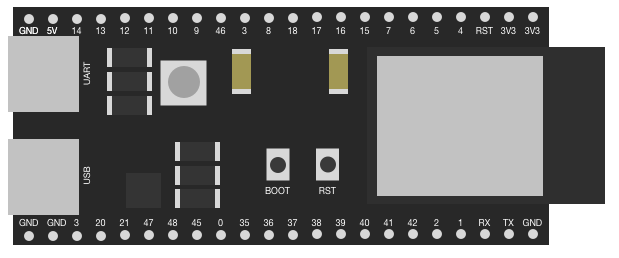
Pin Configuration and Descriptions

The ESP32-S3-DevKit-C features a 2x19 pin header layout. Below is the pin configuration:

Pin Name Type Description
3V3 Power 3.3V power output
GND Power Ground
GPIO0 Input/Output General-purpose I/O, used for boot mode selection
GPIO1 Input/Output General-purpose I/O
GPIO2 Input/Output General-purpose I/O
GPIO3 Input/Output General-purpose I/O
GPIO4 Input/Output General-purpose I/O
GPIO5 Input/Output General-purpose I/O
GPIO6-11 Reserved Reserved for SPI flash memory
GPIO12 Input/Output General-purpose I/O
GPIO13 Input/Output General-purpose I/O
GPIO14 Input/Output General-purpose I/O
GPIO15 Input/Output General-purpose I/O
GPIO16 Input/Output General-purpose I/O
GPIO17 Input/Output General-purpose I/O
EN Input Reset pin (active high)
IOREF Power Reference voltage for I/O pins
VIN Power Input voltage (5V)

Note: Not all GPIO pins support all functions. Refer to the ESP32-S3 datasheet for detailed pin multiplexing information.

Usage Instructions

The ESP32-S3-DevKit-C is easy to use for prototyping and development. Below are the steps to get started:

Setting Up the Development Environment

  1. Install the ESP-IDF (Espressif IoT Development Framework):

    • Download and install the ESP-IDF from the Espressif website.
    • Alternatively, you can use the Arduino IDE with the ESP32-S3 board support package.
  2. Connect the Board:

    • Use a USB Type-C cable to connect the ESP32-S3-DevKit-C to your computer.
    • Ensure the correct drivers are installed for the USB-to-serial interface.
  3. Select the Board:

    • In the Arduino IDE, go to Tools > Board > ESP32 Arduino > ESP32S3 Dev Module.
  4. Upload Code:

    • Write your code in the IDE and upload it to the board.

Example Code: Blinking an LED

Here is an example of how to blink an LED connected to GPIO2 using the Arduino IDE:

// Define the GPIO pin for the LED
#define LED_PIN 2

void setup() {
  // Set the LED pin as an output
  pinMode(LED_PIN, OUTPUT);
}

void loop() {
  // Turn the LED on
  digitalWrite(LED_PIN, HIGH);
  delay(1000); // Wait for 1 second

  // Turn the LED off
  digitalWrite(LED_PIN, LOW);
  delay(1000); // Wait for 1 second
}

Important Considerations and Best Practices

  • Power Supply: Ensure the board is powered with a stable 5V supply via USB or VIN.
  • GPIO Voltage Levels: The GPIO pins operate at 3.3V. Avoid applying 5V directly to the pins.
  • Boot Mode: To enter bootloader mode, hold the BOOT button while pressing the EN button.
  • External Components: Use appropriate pull-up or pull-down resistors for GPIO pins when required.

Troubleshooting and FAQs

Common Issues and Solutions

  1. Board Not Detected by Computer:

    • Ensure the USB cable is functional and supports data transfer.
    • Install the correct USB-to-serial drivers for your operating system.
  2. Code Upload Fails:

    • Check the selected board and port in the Arduino IDE.
    • Hold the BOOT button while uploading the code to force the board into bootloader mode.
  3. Wi-Fi Connection Issues:

    • Verify the SSID and password in your code.
    • Ensure the Wi-Fi network operates on the 2.4 GHz band (not 5 GHz).
  4. GPIO Pin Not Working:

    • Confirm the pin is not reserved for internal functions (e.g., GPIO6-11 for SPI flash).
    • Check for proper wiring and connections.

FAQs

Q: Can I use the ESP32-S3-DevKit-C with MicroPython?
A: Yes, the ESP32-S3 supports MicroPython. You can flash the MicroPython firmware to the board and use it for development.

Q: What is the maximum current output of the 3.3V pin?
A: The 3.3V pin can supply up to 500 mA, depending on the input power source.

Q: Does the board support deep sleep mode?
A: Yes, the ESP32-S3 supports deep sleep mode for low-power applications.

Q: Can I use the board for AI applications?
A: Yes, the ESP32-S3 includes hardware acceleration for AI tasks such as neural network inference and signal processing.

By following this documentation, you can effectively use the ESP32-S3-DevKit-C for your IoT and prototyping projects.